16
Note
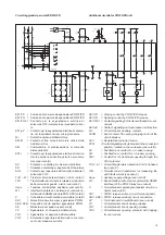
A) Per i circuiti ausiliari dell’interruttore vedere lo schema
specifico dell’interruttore stesso.
B) Il presente schema rappresenta un interruttore in esecu-
zione sezionabile ma è valido anche per gli interruttori in
esecuzione fissa. In tal caso è necessario cortocircuitare
i poli XK4-3 e XK4-4 dello sganciatore PR512/PD; inoltre
i circuiti ausiliari dell’interruttore si attestano ad una
morsettiera denominata XV anzichè al connettore X e alla
morsettiera XZ.
C) Nel caso siano previsti soltanto 2 trasformatori di corrente
sulle fasi L1 e L3 (da utilizzarsi solo con reti a neutro isolato
e correnti di guasto a terra trascurabili), è necessario
cortocircuitare i morsetti XK1-3 e XK1-4 del PR512.
D) La tensione ausiliaria Uaux. è necessaria per garantire che
le seguenti funzioni operino correttamente anche in assen-
za di autoalimentazione (correnti primarie inferiori a 0,2In):
– comando di apertura esterna (SO3) e relative segnala-
zioni (lampada di segnalazione e indicatore ottico)
– misura della corrente
– protezione di guasto a terra e relative segnalazioni
(contatti di segnalazione K51/YO3 e K51/µP, lampada di
segnalazione e indicatori ottici)
– ripristino contatti di segnalazione e indicatori ottici.
La tensione ausiliaria Uaux. è sempre necessaria per
garantire il corretto funzionamento del dialogo (solo per
relè PR512/PD).
La presenza di corrente primaria > 0,2 In su almeno una
fase provvista di trasformatore di corrente garantisce il
corretto funzionamento di tutte le funzioni di protezione,
misura e controllo.
E) Per il collegamento della linea seriale EIA RS485 vedere
la seguente documentazione:
– esempi di distribuzione della comunicazione seriale EIA
RS485 401517
– prescrizioni per la posa del cavo per comunicazione
seriale EIA RS485 601823.
F) Il trasformatore di corrente omopolare TI/O, esterno all’
interruttore e con collegamenti a cura del cliente, è fornito
solo a richiesta. Nel caso il trasformatore TI/O non venga
utilizzato, cortocircuitare i morsetti XK1-7 e XK1-8.
G) I contatti di segnalazione K51/YO3 e K51/µP hanno le
seguenti caratteristiche elettriche:
– massima corrente interrotta
0,8A
– massima tensione interrotta
110Vca - 100Vcc
– massimo carico interrotto a 24Vcc
– induttivo (L/R = 7ms)
10W
– resistivo
24W
– massimo carico interrotto a 48Vac
– induttivo (cos
ϕ
= 0,4)
15VA
– resistivo
30VA.
Collegamenti
Per i collegamenti allo sganciatore PR512 utilizzare i seguenti
tipi di cavo:
– alimentazione ausiliaria (Uaux.) = cavo schermato T14069/
2x0,2 cod. 07108
– comando apertura esterno (SO3) = cavo schermato T14069/
2x0,2 cod. 07108 (lungh. max. 30m)
– input binari S33M e Q/... = cavo schermato T14069/4x0,2
cod. 07109
– input binario S75I = cavo schermato T14069/2x0,2 cod.
07108
Notes
A) For the circuit-breaker auxiliary circuits, see the specific
diagram of the circuit-breaker itself.
B) This diagram shows a withdrawable version circuit-breaker
but is also valid for fixed version circuit-breakers. In that
case, it is necessary to short-circuit poles XK4-3 and XK4-
4 of the PR512/PD release. Moreover, the circuit-breaker
auxiliary circuits are terminated at a terminal board called
XV instead of at connector X and at terminal board XZ.
C) When only 2 current transformers are provided on phases
L1 and L3 (only to be used with networks with insulated
neutral and negligible earth fault currents), terminals XK1-
3 and XK1-4 of the PR512 must be short-circuited.
D The Uaux. auxiliary power supply is needed to guarantee
that the following functions operate correctly even without
self-supply (primary currents lower than 0.2 In):
– external opening control (SO3) and relative signals
(signalling lamp and optic indicator)
– current measurement
– earth fault protection and relative signals (K51/YO3 and
K51/mP signalling contacts, signalling lamp and optic
indicators)
– reset of signalling contacts and optic indicators.
The Uaux. auxiliary power supply is always needed to
guarantee correct dialogue operation (only for PR512/PD
relay).
The presence of primary current > 0.2 In on at least one
phase fitted with current transformer ensures correct op-
eration of all the protection, measuring and control func-
tions.
E) For connection of the EIA RS485 serial line, see the
following documentation:
– examples of distribution of the EIA RS485 serial commu-
nication 401517
– requirements for cable laying for serial EIA RS485 serial
communication 601823.
F) The TI/O homopolar current transformer, outside the cir-
cuit-breaker and with connections to be made by the
customer, is only supplied on request. Should the TI/O
transformer not be used, short-circuit terminals XK1-7 and
XK1-8.
G) The K51/YO3 and K51/mP signalling contacts have the
following electrical characteristics:
– maximum interrupted current
0.8 A
– maximum interrupted voltage
110Vac - 100Bdc
– maximum interrupted load at 24Vdc
– inductive (L/R = 7 ms)
10W
– resistive
24W
– maximum interrupted load at 48Vac
– inductive (cos
ϕ
= 0.4)
15VA
– resistive
30VA.
Connections
For connections to the PR512 release use the following types
of cables:
– auxiliary power supply (Uaux.) = screened cable T14069/
2x0.2 code 07108
– external opening control (SO3) = screened cable T14069/
2x0.2 code 07108 (30m max. length)
– binary inputs S33M, Q/... = screened cable T14069/4x0.2
code 07109
– binary input S75I = screened cable T14069/2x0.2 code
07108


