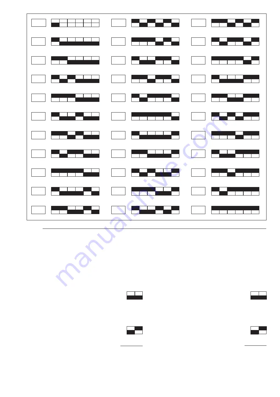
7
OFF
0,200xIn
0,225xIn
0,250xIn
0,275xIn
0,300xIn
0,325xIn
0,350xIn
0,375xIn
0,400xIn
0,425xIn
0,450xIn
0,475xIn
0,500xIn
0,525xIn
0,550xIn
0,575xIn
0,625xIn
0,650xIn
0,675xIn
0,700xIn
0,725xIn
0,750xIn
0,775xIn
0,800xIn
0,825xIn
0,850xIn
0,875xIn
0,900xIn
0,925xIn
0,950xIn
0,975xIn
1,000xIn
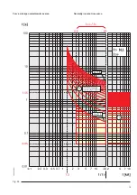
Fig. 2
3.1.2. Selection of the type of curve
Four different time-current relations can be selected by means
of the dip-switches indicated in fig. 1 ref. 3. The sum of the
selected values indicates the type of curve selected.
N.B. To define the K parameter, see paragraph 3.1.3.
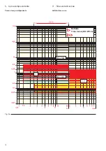
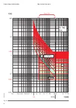
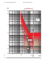
Definite time curve (DT): (ß=2) (see fig. 9 a)
Set the dip-switches as follows:
Mathematical relation to find t>:
t> = K x 2
Inverse time curve (NI): a=0.02; ß>=0.14 (see fig. 9 b)
Set the dip-switches as follows:
0.14
Mathematical relation to find t>:
t> = K x
[I/I>]
0,02
- 1
where I represents the overload current and I> the set thresh-
old current.
3.1.2. Scelta del tipo di curva
Possono essere selezionate quattro diverse relazioni tempo-
corrente, mediante i dip switch indicati in fig. 1 rif. 3.
La somma dei valori selezionati indica il tipo di curva prescelto.
N.B. Per la definizione del parametro K vedere paragrafo
3.1.3.
Curva a tempo indipendente (DT): (ß=2) (vedi fig. 9 a)
Predisporre i dip-switch in questo modo:
Relazione matematica per trovare t>:
t> = K x 2
Curva a tempo inverso (NI): a=0,02; ß=0,14 (vedi fig. 9 b)
Predisporre i dip-switch in questo modo:
0,14
Relazione matematica per trovare t>:
t> = K x
[I/I>]
0,02
- 1
dove I rappresenta la corrente di sovraccarico e I> la corrente
di soglia regolata.


