background image

Parameters   41

No.

Name/Value/Range

Description

Default

FbEq (16b/32b)

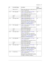
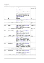
104 Warnings and faults

104.01

Tripping fault

Fault which actually caused the inverter to trip, as 
it arrived at the trip register.

-

1 = 1

104.02

Active fault 2

2nd active fault in the trip register.

-

1 = 1

104.03

Active fault 3

3rd active fault in the trip register.

-

1 = 1

104.04

Active fault 4

4th active fault in the trip register.

-

1 = 1

104.05

Active fault 5

5th active fault in the trip register.

-

1 = 1

104.06

Active warning 1

1st active warning in the warning register.

-

1 = 1

104.07

Active warning 2

2nd active warning in the warning register.

-

1 = 1

104.08

Active warning 3

3rd active warning in the warning register.

-

1 = 1

104.09

Active warning 4

4th active warning in the warning register.

-

1 = 1

104.10

Active warning 5

5th active warning in the warning register.

-

1 = 1

104.11

Latest fault

Latest fault in the trip log store. The trip log store 
is loaded with the active faults in the order they 
occur.

-

1 = 1

104.12

2nd latest fault

2nd fault in the trip log store.

-

1 = 1

104.13

3rd latest fault

3rd fault in the trip log store.

-

1 = 1

104.14

4th latest fault

4th fault in the trip log store.

-

1 = 1

104.15

5th latest fault

5th fault in the trip log store.

-

1 = 1

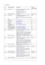
104.16

Latest warning

Latest warning in the warning log store. The 
warning log store is loaded with the active 
warnings in the order they occur.

-

1 = 1

104.17

2nd latest warning

2nd warning in the trip log store.

-

1 = 1

104.18

3rd latest warning

3rd warning in the trip log store.

-

1 = 1

Summary of Contents for PRO-33.0-TL Series

Page 1: ...ABB solar inverters Service menu guide PRO 33 0 TL string inverters ...

Page 2: ... up guide 3AUA0000123263 PRO 33 0 TL product manual 3AUA0000123261 PRO 33 0 TL service menu guide 3AXD50000015823 Option manuals and guides FIO 01 Digital I O Extension user manual 3AFE68784921 VSN700 Data Logger 9AKK106103A7625 FIO 11 User s Manual 3AFE68784930 FENA 01 11 21 Ethernet adapter module user s manual 3AUA0000093568 FSCA 01 RS 485 adapter module User s manual 3AUA0000109533 Drive compo...

Page 3: ...ce menu guide PRO 33 0 TL string inverters 3AXD50000015823 Rev C EN EFFECTIVE 2017 06 29 2017 ABB Oy All Rights Reserved 1 Service menu 2 Program features Table of contents 3 Parameters 4 Fieldbus interfaces ...

Page 4: ......

Page 5: ...oring 20 Combinatory limit 21 Rate of change of frequency 21 Active anti islanding 21 External grid monitoring relay 21 Reactive power control 22 Active power limitations 23 External active power limit 23 Limitation after grid connection and after grid fault 23 Limitation based on grid frequency 24 Limitation based on grid voltage 27 Flat top limit 28 Power gradient 28 String monitoring 29 Reverse...

Page 6: ...ion 87 184 Logger setup 88 188 Grid monitoring 89 189 Inverter control 94 190 External measurements 95 196 System 96 202 Fan settings 98 209 Misc 99 4 Fieldbus interfaces Contents of this chapter 101 Fieldbus adapter modules 101 Embedded fieldbus 101 Connecting inverter to fieldbus network 101 Setting up embedded fieldbus interface 102 Accessing inverter parameters 102 Data I O registers 0 68 102 ...

Page 7: ... composer entry 111 Drive composer pro 111 6 Firmware update Contents of this chapter 113 Updating inverter firmware 114 Preparing before firmware update 114 Downloading firmware 115 Confirming inverter operation 117 Restoring backup 117 Firmware loading troubleshooting 117 Updating control unit firmware 119 Troubleshooting the control unit 120 Reattempt option 1 restart update procedure 120 Reatt...

Page 8: ...8 ...

Page 9: ...er features are accessible only from the Service menu For example you can make custom settings for countries that are not defined in the inverter software or adjust the inverter s operating parameters to better meet the local requirements Accessing Service menu 1 From the screen saver display or output view screen simultaneously push the left soft key right soft key and Help button If you push one...

Page 10: ...menu 2 Enter the PIN 6988 Use the up left and right arrows to enter the digits Press the right soft key to save 3 Scroll down the menu and enter the Service submenu The heading Parameters is now shown on the list ...

Page 11: ...nd you exit the Service menu To return to the Service menu see Accessing Service menu on page 9 If an assistant is active or waiting for a response from the user the screen saver does not turn on Before using the Service menu increase the preset screen saver delay so you do not need to repeatedly access the menu This is useful especially when the delay is short You can change the screen saver dela...

Page 12: ...12 Service menu ...

Page 13: ...rameters and related faults and warnings wherever applicable See Control and monitoring interfaces page 14 Operational description page 14 DC voltages and maximum power point tracking page 15 Grid monitoring page 19 Reactive power control page 22 Active power limitations page 23 String monitoring page 29 Autoreset page 31 Fault history page 32 Temperature control page 33 Fan service page34 ...

Page 14: ...tation is active the inverter is in the Limited state while the inverter produces energy to the grid When the DC power level from panels is low the inverter is in the Sleep or Standby state depending on the night mode settings parameter 189 07 Night mode Connection tests is a state the inverter goes through every time it connects to the grid and performs tests for DC voltage and internal protectio...

Page 15: ...950 V it is regulated down to 950 V where tracking is started 5 Available power is less than the inverter s power limit Pact Plim 6 Inverter disabled parameter 189 01 Inverter operation OR fault OR grid unstable OR VDC low OR VDC VDCmax OR FRT overshoot 7 No monitoring mode parameter 189 07 Night mode AND VDC VDCsleep AND Control unit screensaver active AND No events active 8 Inverter disabled par...

Page 16: ...f is 550 V and nominal value for the VMPPT_min is 580 V 400 VAC The inverter topology is a single stage inverter which means that the inverter does not have a DC DC booster Thus the inverter startup voltage and minimum maximum power point voltage depends linearly on the AC output voltage If the available PV power is greater than the derated power of the inverter MPP tracking is disabled and DC vol...

Page 17: ...ion delays anti islanding settings reactive power settings fault ride through settings power limitation settings and MPPT recovery settings Usually the country code is not changed during the lifetime of the inverter You can change the country code with parameter 188 01 Country code Note Changing this value will always override any changes made in the above mentioned parameter groups When a country...

Page 18: ...rter and save the parameter changes to permanent memory 1 Set parameter 189 01 Inverter operation to Enable 2 Refresh the settings by setting the parameter 188 05 Refresh 3 Save parameter values by setting the parameter 196 07 Param save ...

Page 19: ...oltage source that can be set to Main or Phase respectively The settings for grid monitoring are set in relation to the nominal value Settings 188 02 Nominal LL voltage 188 03 Nominal phase voltage 188 04 Nominal frequency 188 06 Voltage source Connection delays Typically it is required that the grid must be stable for some time before grid connection is allowed For this purpose there is a set of ...

Page 20: ...able parameter a limit parameter and a time parameter When the limit is enabled and the measured value exceeds the limit for the time the grid is declared as unstable All limits are logically connected in parallel Each phase main voltage is independently monitored Settings 188 50 Undervoltage enable 1 188 71 Overvoltage time 3 Sliding overvoltage Sliding overvoltage implements the monitoring of th...

Page 21: ...rt of the grid even though the power from the utility grid is cut off Islanding can be dangerous to people working with the grid and not realizing that the circuit is still powered For that reason distributed power generators such as solar inverters must detect an island situation and immediately stop feeding power to the grid The anti island function is based on a so called active method whereby ...

Page 22: ...pe The actual reactive reference value for the selected type must be written to the parameter 124 01 User Qref When parameter 124 06 Q power ref type is set to Q x regulation curve parameter 124 30 Q x curve is used to select the curve type Examples of different curve types are shown below Lock in and lock out conditions define when the selected curve is active The curve is defined with six points...

Page 23: ...imitation after grid connection and after grid fault Active power can be limited after grid connection and after grid fault The limitation type is selected with parameter 130 70 Connect limit type The limitation can be set to be active always only after grid fault or never There are different ramp rates for grid connections and re connections after grid faults Limitation ramp starts from 0 Ramp is...

Page 24: ... crossed the power value is saved and the power limit is calculated in relation to that power The limit may decrease only until the frequency drops below the value defined in parameter 130 65 P f release frequency Then the power limit is ramped up with the parameter 130 67 P f release ramp in relation to the nominal power Settings 130 62 P f limit type 130 63 P f corner frequency 130 64 P f limit ...

Page 25: ...quencies above the corner frequency When the frequency drops below 130 63 P f corner frequency power limit is ramped up with the parameter 130 67 P f release ramp in relation to nominal power Settings 130 62 P f limit type 130 63 P f corner frequency 130 64 P f limit gradient 130 67 P f release ramp 1 3 0 6 4 P f l i m i t g r a d i e n t 130 62 P f limit type Free running Plim Power at the time o...

Page 26: ...er values as frequency increases It stays at its current lowest value as long as the frequency remains above the corner frequency defined in parameter 130 63 P f corner frequency As the frequency decreases and passes through the corner frequency a release delay is started The 130 66 P f release time must elapse before the power limit is ramped up with 130 67 P f release ramp in relation to the nom...

Page 27: ...down to 130 79 P U limit level Parameter 130 80 P U limit ramp defines the slope of the ramp down from the P U triggering level falls below the 130 78 P U release level power limit is released and active power ramps upwards as defined by parameter130 81 P U release ramp Settings 130 77 P U trigger level 130 78 P U release level 130 79 P U limit level 130 80 P U limit ramp 130 81 P U release ramp 1...

Page 28: ...flat top Note that Flat top works just like a constant active power limit Settings 130 90 Flat top limit Power gradient The power gradient function limits the rate of rise in active power to a predefined value This has the effect of stabilizing the grid as the power cannot change too rapidly The power gradient function can be enabled with parameter 130 92 Active power ramping and the rate of rise ...

Page 29: ...everse input current detection 174 31 Reverse input current limit 174 32 Reverse input current delay 101 30 Input current Reverse string current detection SX model If reverse current is detected in one of the connected strings a warning is indicated The threshold value is initially set in parameter 174 13 Reverse string current limit so that it recognizes the reverse current direction Reverse curr...

Page 30: ...ype The reference value can be selected to be either the maximum or the mean value of the connected strings In absolute mode individual string currents are compared against the reference value in amperes If the difference is greater than the value set in parameter 174 19 Absolute current limit in amperes a warning is indicated after a delay In relative comparison mode individual string currents ar...

Page 31: ...ions The table below shows the category 1 faults These faults have two parameters one for setting the total number of counts the autoreset function can clear reset the fault before it becomes permanent one for controlling the time period between consecutive reset attempts Note When the inverter is connected to the grid for more than 10 seconds all autoreset counts are reset to zero and allows to r...

Page 32: ...can be configured with any fault codes that may be needed by the user to be automatically reset The table below shows the category 2 faults Diagnostics 132 02 Autoreset boot counter Fault history The inverter fault history is accessed from the Events menu or from parameter group 104 Warnings and faults In the Events menu active faults and warnings are shown under separate submenus All faults are s...

Page 33: ...e limit and current limitation is activated If the temperature of the inverter continues to increase a fault is triggered and the inverter disconnects The fault has to be reset manually Diagnostics 130 04 Limit word 4 bit3 CB temperature bit4 inverter temperature bit5 filter temperature 173 06 Internal fan speed 173 07 External fan 1 speed 173 08 External fan 2 speed 173 23 Control board temperatu...

Page 34: ... fans are not running when they should be In that case the inverter continues operation but may limit the output power or may trip due to overtemperature Resetting fan run time counters See PRO 33 0 TL Product manual 3AUA0000123261 English for information on how to replace the fans Note that the inverter must be stopped and disconnected from the grid when the fans are replaced After replacing the ...

Page 35: ...to confirm that you have completed the Fan service assistant and return to the menu Diagnostics 173 03 Internal fan run time 173 04 External fan 1 run time 173 05 External fan 2 run time 173 06 Internal fan speed 173 07 External fan 1 speed 173 07 External fan 2 speed ...

Page 36: ...36 Program features ...

Page 37: ...tus An actual value is the result of a measurement or calculation by the inverter or it contains status information Compatibility The parameters described in this section are compatible with firmware version KLUF0 v1 72 Earlier firmware releases does not support all parameters described in this document If a parameter is not visible when using the control unit or the Drive composer configuration t...

Page 38: ...ue is not applicable 0 2 000 V Value range and unit 10 1 V 100 1 V 10 1 V means 16 bit access with one decimal 100 1 V means 32 bit access with two decimals 1000 1 Mohm A dash means 16 bit access is not possible 1000 1 Mohm means 32 bit access only with three decimals 1 1 mA 16 bit and 32 bit access are identical integers only 158 04 Baud rate For parameters with a set of fixed selection options t...

Page 39: ...rrent Calculated reactive current 100 100 10 1 A 100 1 A 101 07 Reactive current Reactive current in percent of the nominal current 200 200 1 1 10 1 101 08 Frequency Measured grid frequency 0 100 Hz 100 1 Hz 101 09 Grid voltage Calculated average line to line grid voltage based on voltage measurements 0 2 000 V 1 1 V 100 1 V 101 10 Apparent power Apparent output power of the inverter 0 50 10 1 kVA...

Page 40: ...6 CosPhi Power factor 1 1 100 1 101 20 Converter current Measured converter current 0 100 10 1 A 100 1 A 101 21 Converter current Measured converter current in percent of the nominal current 0 200 1 1 10 1 101 30 Input current Measured input current 0 100 A 10 1 A 100 1 A No Name Value Range Description Default FbEq 16b 32b ...

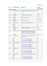
Page 41: ...ive warning in the warning register 1 1 104 09 Active warning 4 4th active warning in the warning register 1 1 104 10 Active warning 5 5th active warning in the warning register 1 1 104 11 Latest fault Latest fault in the trip log store The trip log store is loaded with the active faults in the order they occur 1 1 104 12 2nd latest fault 2nd fault in the trip log store 1 1 104 13 3rd latest fault...

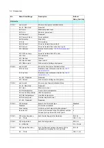
Page 42: ...42 Parameters 104 19 4th latest warning 4th warning in the trip log store 1 1 104 20 5th latest warning 5th warning in the trip log store 1 1 No Name Value Range Description Default FbEq 16b 32b ...

Page 43: ...meters Product name1 Product name6 into a string Each parameter contains 4 ASCII characters represented as a 32 decimal number 0 1 1 107 36 Product name7 See parameter 107 30 Product name1 1 1 107 40 Product serial number1 Holds part of the serial number of the inverter The serial number is obtained by concatenating parameters Product serial number1 Product serial number6 into a string Each parame...

Page 44: ...ameter depends on the number of digital input outputs on the extension module Example 00001001b DIO1 and DIO4 are on remainder are off This parameter is read only 1 1 114 09 DIO1 configuration Visible only when parameter 114 01 Option module 1 type is FIO 01 or FIO 11 Selects whether DIO1 of the extension module is used as a digital input or output Input Output DIO1 is used as a digital output 0 I...

Page 45: ...1 DIO3 output source Visible onlt when parameter 114 01 Option module 1 type is FIO 01 Selects an inverter signal to be connected to digital input output DIO3 of the extension module when parameter 114 19 DIO3 configuration is set to Output For the available selections see parameter 114 11 DIO1 output source Off 114 24 DIO4 configuration Visible only when parameter 114 01 Option module 1 type is F...

Page 46: ...he I O extension module The hardware setting is shown by parameter 114 29 AI1 HW switch position mA mA milliamperes 0 V voltage 1 114 31 RO status Visible only when parameter 114 01 Option module 1 type is FIO 01 Status of relay outputs on the I O extension module Example 00000001b RO1 is energized RO2 is de energized 0000h FFFFh Status of relay outputs 1 1 114 33 AI1 min Visible only when paramet...

Page 47: ...lable selections see parameter 114 11 DIO1 output source Off 114 41 AI2 actual value Visible only when parameter 114 01 Option module 1 type is FIO 11 Displays the value of analog input AI2 in mA or V depending on whether the input is set to current or voltage This parameter is read only 22 000 22 000 mA or V Value of analog input AI2 1000 1 mA or V 114 42 AI2 scaled value Visible only when parame...

Page 48: ...ue that corresponds to the minimum analog input AI2 value defined by parameter 114 48 AI2 min 0 000 32768 000 32767 000 Real value corresponding to minimum AI2 value 1 1 114 51 AI2 scaled at AI2 max Visible only when parameter 114 01 Option module 1 type is FIO 11 Defines the real value that corresponds to the maximum analog input AI2 value defined by parameter 114 49 AI2 max See the drawing at pa...

Page 49: ...odule 1 type is FIO 11 Defines the minimum value for analog input AI3 0 000 mA or V 22 000 22 000 mA or V Minimum value of AI3 1000 1 mA or V 114 64 AI3 max Visible only when parameter 114 01 Option module 1 type is FIO 11 Defines the maximum value for analog input AI3 10 22 000 22 000 mA or V Maximum value of AI3 1000 1 mA or V 114 65 AI3 scaled at AI3 min Visible only when parameter 114 01 Optio...

Page 50: ...O1 output value defined by parameter 114 82 AO1 out at AO1 src min 0 0 32768 0 32767 0 Real signal value corresponding to minimum AO1 output value 1 1 114 81 AO1 source max Visible only when parameter 114 01 Option module 1 type is FIO 11 Defines the real value of the signal selected by parameter 114 77 AO1 source that corresponds to the maximum AO1 output value defined by parameter 114 83 AO1 out...

Page 51: ...ing is used to avoid heating the sensor 0 20 mA 10 1 mA 117 13 PT sensor input Sets from which input PT sensor temperature signal is read None 0 0 AI1 114 26 AI1 actual value page 45 1 AI2 114 41 AI2 actual value page 47 2 AI3 114 56 AI3 actual value page 48 3 117 14 Temperature 2 input Sets from which input temperature signal is read None 0 0 AI1 114 26 AI1 actual value page 45 1 AI2 114 41 AI2 a...

Page 52: ...act ref max Maximum value of reactive current reference in percent 105 0 200 1 1 10 1 124 12 Ireact ref min Minimum value of reactive current reference in percent 105 200 0 1 1 10 1 124 13 Ireact ref lim Output value of reactive power reference limitation Limitation based on 124 11 Ireact ref max and 124 12 Ireact ref min values 200 200 1 1 10 1 124 14 Ireact ref ramp up Reactive current ramp up t...

Page 53: ...is set to the value defined by parameter 124 39 Q x output level 1 0 1 1 100 1 124 38 Q x input level 6 See parameter 124 33 Q x input level 1 124 39 Q x output level 1 Defines the first reference output value for the Q x regulation curve When the selected input signal reaches 124 33 Q x input level 1 the reactive power reference is set to the value defined by this parameter 0 1 1 100 1 124 44 Q x...

Page 54: ...f min Reactive power reference is limited by 124 12 Ireact ref min b2 b14 Reserved Reserved b15 Current Grid current is limiting reactive power 130 04 Limit word 4 Shows current based limitation status b0 b1 Reserved Reserved b2 I max Maximum current b3 CB temperature Control board temperature b4 Inverter temperature IGBT temperature b5 Filter temperature Line filter temperature b6 Nominal power N...

Page 55: ...ting to grid Off Off No active power ramping after grid connection 0 After grid fault Power ramping is active only after grid fault 1 Always Power ramping is active always when connecting to grid 2 130 71 Connect limit ramp Sets the active power ramp that is used after connecting to grid 10 min 0 600 min 1 1 min 130 72 Grid fault ramp Sets the ramp that is used in reconnection after grid fault 10 ...

Page 56: ...ction Disable Disable 0 Enable 1 130 93 Active power ramp Sets the active power ramp rate 100 min 0 1000 min 1 1 min 130 94 Shut down ramp Sets the active power ramp that is applied in a controlled shut down 100 s 0 1000 s 1 1 s 130 98 External limit ramp up Sets the ramp up time for 130 75 External power limit 0 ms 0 60 000 ms 1 1 ms 130 99 External limit ramp down Sets the ramp down time for 130...

Page 57: ...5 0 20 1 1 132 04 Overcurrent reset delay Sets the delay for overcurrent autoreset 10 s 1 3000 s 1 1 s 132 05 DC protection trials Number of DC protection autoreset trials 3 0 20 1 1 132 06 DC protection reset delay Sets the delay for DC protection autoreset 10 s 1 3000 s 1 1 s 132 07 Ground impedance trials Sets the number of ground impedance autoreset trials 50 0 100 1 1 132 08 Ground impedance ...

Page 58: ...y need to be reconnected manually Done Done Refresh done 0 Configure Refresh parameters 149 01 and 149 03 The value reverts automatically to Done 1 149 20 Terminal X1 X8 Shows currently active protocol on terminals X1 and X8 Note Terminals X1 and X8 are internally connected and share the same UART Terminal X1 is intended for connecting the remote PVS AP L control unit This parameter is read only C...

Page 59: ...or secondary control unit protocol when activated on terminal X2 When the secondary control unit protocol is activated it is assigned a node ID equal to the Modbus RTU ID This allows to retain any network topology already present defined for RS 485 communication bus 1 1 32 1 1 149 24 Control unit 2 baud rate Visible only when parameter 149 21 Control unit 2 Sets the baud rate for secondary control...

Page 60: ...16b 32b 150 FBA 150 01 FBA A Enable Enables communication between the inverter and fieldbus adapter A Disable Disable Communication between inverter and fieldbus adapter A disabled 0 Option slot 2 Communication between inverter and fieldbus adapter A enabled 1 ...

Page 61: ...le 5 MB UDP T16 M Modbus over UDP Transparent 16 bit profile 6 MB UDP T32 M Modbus over UDP Transparent 32 bit profile 7 151 02 Profile Visible only when parameter 151 01 FBA type is FSCA 01 Selects the communication profile for the network connection Note Applicable only with profiles Transp 10 and Transp 32 Transp 16 ABB Classic Modbus RTU protocol with ABB Drives profile Classic 0 ABB Enhanced ...

Page 62: ...ings must be used in all on line stations 8 None 1 8 None 1 No parity bit one stop bit 8 data bits 0 8 None 2 No parity bit two stop bit 8 data bits 1 8 Even 1 Even parity indication bit one stop bit 8 data bits 2 8 Odd 1 Odd parity indication bit one stop bit 8 data bits 3 151 06 IP address 2 Visible only when parameter 151 01 FBA type is FENA 11 21 Second octet of FENA IP address 0 255 0 151 06 ...

Page 63: ... Shows the number of valid messages that the inverter has received 0 0 65535 Number of valid messages 151 09 Subnet CIDR Visible only when parameter 151 01 FBA type is FENA 11 21 Subnet masks are used for splitting networks into subnets A subnet mask is a 32 bit binary number that is used to split the IP address into a network address and a host address Here the subnet mask is represented by its C...

Page 64: ... FENA 11 21 Second octet gateway of IP address 0 255 0 151 11 Word order Visible only when parameter 151 01 FBA type is FSCA 01 Selects the order in which 16 bit registers of 32 bit parameters are transferred For each register 16 bit the first byte contains the high order byte and the last byte contains the low order byte HiLo LoHi The first register contains the low order word and the second regi...

Page 65: ...1 Sets the bit rate for the Ethernet interface X2 FENA 21 only Auto Auto Auto negotiate 0 100 Mbps FD 100 Mbps full duplex 1 100 Mbps HD 100 Mbps half duplex 2 10 Mbps FD 10 Mbps full duplex 3 10 Mbps HD 10 Mbps half duplex 4 151 20 Timeout time Visible only when parameter 151 01 FBA type is FENA 11 21 Sets a timeout after which communication status parameter 151 31 goes to Off line state unless a...

Page 66: ...eter 151 01 FBA type is FENA 11 21 Defines the mapping between inverter parameters and Modbus holding registers Note Changes are effective only when settings are refreshed or the device is power cycled Mode 0 Mode 0 Both 16 bit and 32 bit access is possible for parameter groups 101 199 indexes 1 99 RegisterAddress for 16bit access 100 ParamGroup ParamIndex RegisterAddress for 32bit access 20000 20...

Page 67: ... Configure Refreshing 1 151 28 Par table ver Adapter parameter table version internal use 151 29 Drive type code Adapter inverter type code Internal use 620 151 30 Mapping file ver Mapping file version Internal use 151 31 D2FBA comm sta Displays the communication status of the adapter module Idle Idle Adapter is not configured 0 Exec Init Adapter is initializing 1 Time out A timeout has occurred i...

Page 68: ...68 Parameters 151 33 FBA appl SW ver Shows the application program revision of the adapter module No Name Value Range Description Default FbEq 16b 32b ...

Page 69: ...er s manual Note FBA data in 1 12 are for reading out data from the inverter to the fieldbus master None None 0 CW 16bit Currently not in use 1 Ref1 16bit Currently not in use 2 Ref2 16bit Currently not in use 3 SW 16bit Currently not in use 4 Act1 16bit Currently not in use 5 Act2 16bit Currently not in use 6 CW 32bit Currently not in use 7 Ref1 32bit Currently not in use 8 Ref2 32bit Currently n...

Page 70: ...ter of the inverter Note FBA data out 1 12 are for writing data into parameter groups of the inverter None None 0 CW 16bit Currently not in use 1 Ref1 16bit Currently not in use 2 Ref2 16bit Currently not in use 3 CW 32bit Currently not in use 4 Ref1 32bit Currently not in use 5 Ref2 32bit Currently not in use 6 CW2 16bit Currently not in use 7 Other Selects destination i e internal parameter grou...

Page 71: ... Autodetect Automatic baud rate detection 0 9 6 kbps Force baud rate to 9 600 bps 2 19 2 kbps Force baud rate to 19 200 bps 3 38 4 kbps Force baud rate to 38 400 bps 4 57 6 kbps Force baud rate to 57 600 bps 5 76 8 kbps Force baud rate to 76 800 bps 6 115 2 kbps Force baud rate to 115 200 bps 7 158 05 Parity Selects the character framing bits per character start stop bits parity for RS485 bus Note...

Page 72: ...ate address might be present on the bus b10 Comm loss 1 Zero packets of any type addressed to device during the configured timeout period To know when this feature is active see parameter 158 12 and 158 12 b11 CW Ref loss 1 Zero writes to the control or reference points have occurred during the configured timeout period See parameter 158 12 b12 Not active Not in use b13 Protocol 1 b14 Protocol 2 b...

Page 73: ...bit access 100 ParamGroup 100 ParamIndex RegisterAddress for 32bit access 20000 200 ParamGroup 100 2 ParamIndex 6 Mode 7 Only 32bit access is possible for parameter groups 101 227 indexes 1 255 RegisterAddress 512 ParamGroup 100 2 ParamIndex Note Only this mode can access all parameter values 7 158 34 Word order Selects the order in which 16 bit registers of 32 bit parameters are transferred Note ...

Page 74: ...02 Disconnect diagnostic Shows the reason for last disconnection Reverts to value No disconnection when the inverter connects back to grid Inverter disabled Inverter operation disabled 100 DC undervoltage DC voltage too low 300 Faulted Fault activated 600 No disconnection Inverter is connected to the grid or has not performed disconnection 700 Grid overvoltage Grid voltage too high 410 Grid underv...

Page 75: ...e 2nd latest connection time 172 08 Connection 3 date 3rd latest connection date 172 09 Connection 3 time 3rd latest connection time 172 10 Connection 4 date 4th latest connection date 172 11 Connection 4 time 4th latest connection time 172 12 Connection 5 date 5th latest connection date 172 13 Connection 5 time 5th latest connection time 172 20 Grid monitoring SW1 Shows grid monitoring status wor...

Page 76: ...age 3 b15 Sliding overvoltage 172 22 Grid monitoring SW3 Shows the grid monitoring status word 3 SW3 0 Inactive status 1 Active status triggered or enabled b0 Combinatory limit b1 Reserved b2 RoCoF b3 b6 Reserved b7 Anti islanding b8 b15 Reserved No Name Value Range Description Default FbEq 16b 32b ...

Page 77: ...m 173 08 External fan 2 speed Shows RPM of external fan 2 located on the left side of the inverter 0 rpm 0 10 000 rpm 1 1 rpm 173 18 Power up tests Shows number of times the inverter was powered up 0 4294967295 1 1 173 19 Connection tests Shows number of grid connection tests 0 0 4294967295 1 1 173 20 Grid connections Shows amount of grid connections 0 0 4294967295 1 1 173 21 Ground impedance Zn S...

Page 78: ... RCMU 1000 1000 mA 1 1 mA 173 34 RCMU test current Shows test current used for self test of the RCMU 0 0 mA 325 0 325 0 mA 10 1 mA 173 36 Ground current meas diff RMS Shows difference between monitoring channels The system uses two separate channels for obtaining the residual current reading from the RCMU A fault is raised if the difference is too big 0 0 0 1000 0 mA 1 1 10 1 mA 173 80 Control uni...

Page 79: ...s a string combiner with DC fuses Disable Disable 0 Enable 1 174 15 String monitor delay Sets the duration of how long the current deviation must be above limit before defined action of the string monitor is triggered 1 min 0 1440 min 1 1 min 174 16 Comparison mode Selects the comparison mode of the string current deviation detection Relative Absolute The string current deviation is detected by co...

Page 80: ...t limit Sets the reverse input current detection limit 1 A 0 1 5 A 100 1 A 174 32 Reverse input current delay Sets the duration for how long the reverse input current must be above the limit before indicating a fault 10 s 0 600 s 1 1 s 174 35 Reverse string current threshold Sets the activation power level in percent of the nominal power for reverse string current detection 10 0 100 1 1 174 36 Rev...

Page 81: ...g 5 15 15 A 100 1 A 174 55 Current 6 Measured current of string 6 15 15 A 100 1 A 174 56 Current 7 Measured current of string 7 15 15 A 100 1 A 174 57 Current 8 Measured current of string 8 15 15 A 100 1 A No Name Value Range Description Default FbEq 16b 32b ...

Page 82: ...l output power where MPPT considers power to equal 0 and starts to reduce the DC voltage This avoids MPPT from drifting at voltages above the panel open circuit voltage 1 0 10 1 1 178 50 MPPT status word Shows the MPPT status word b0 MPPT MPPT is active b1 Limited mode Tracking is not active because active power is limited b2 Minimum voltage MPPT reference is at the minimum voltage b3 Maximum volt...

Page 83: ...en energy is produced by a solar plant instead of a conventional fossil fueled plant The value is calculated by multiplying produced energy with a conversion factor CO2 reduction factor 0 2147483 t 1 1 t 1000 1 t 179 02 CO2 reduction factor Sets the conversion factor to calculate CO2 reduction from produced energy 0 7 0 65500 1 1 t 1000 1 t ...

Page 84: ...scription Default FbEq 16b 32b 180 Day production 180 01 Hour 0 energy Shows energy produced during the first hour of current day 0 655 kWh 1 1 kWh 100 1 kWh 180 24 Hour 23 energy Shows energy produced during the last hour of current day ...

Page 85: ...ription Default FbEq 16b 32b 181 Month production 181 01 Day 1 energy Shows energy produced during the first day of current month 0 279000 kWh 1 1 kWh 10 1 kWh 181 31 Day 31 energy Shows energy produced during the last day of current month ...

Page 86: ...scription Default FbEq 16b 32b 182 Year production 182 01 Month 1 energy Shows energy produced during the first month of current year 0 279000 kWh 1 1 kWh 182 12 Month 12 energy Shows energy produced during the last month of current year ...

Page 87: ...produced in one year for all of product lifetime after first start up 0 279000 kWh 1 1 kWh 183 24 Year 23 energy See parameter 183 01 Year 0 energy 183 25 Energy counter resettable Shows total produced energy since last reset Writing 0 resets the counter 0 kWh 100 1 kWh 183 26 Total Energy Shows total produced energy 1 1 kWh ...

Page 88: ...y logging Days since 1 1 1980 0 43440 days 1 1 day 184 02 Last Boot Time Days Shows the date saved at power failure to update loggers accordingly in the next power up This date indicates the day when device was shut down 0 65500 days 1 1 day 184 03 Last Boot Time Ticks Shows the time saved at power failure to update energy loggers accordingly in the next power up 0 864000000 1 1 ...

Page 89: ...voltage to be used for checking grid voltage limits Main Main 0 Phase 1 188 10 Initial connection delay Sets time delay for initial grid connection 5 s 1 1 s 188 11 Reconnection delay Sets reconnection time delay 300 s 1 1 s 188 12 Quick disturbance limit Sets limit for quick disturbance protection 0 s 1 1 s 188 13 Quick reconnection delay Sets quick reconnection time delay 5 s 1 1 s 188 16 Extern...

Page 90: ...above the limit When disabled limit is not checked Disable Disable 0 Enable 1 188 25 Connect undervoltage limit Sets the limit that is used only when the inverter is not connected The limit is disabled when the inverter is connected The purpose is to allow different connect and disconnect limits See parameter 188 24 Connect undervoltage type 80 1 1 188 26 Connect overvoltage type Defines how 188 2...

Page 91: ...2 Sets limit for overfrequency protection 1 Hz 0 30 Hz 1 1 Hz 10 1 Hz 188 45 Overfrequency time 2 Sets trip time for overfrequency protection 100 ms 0 120 000 ms 1 1 ms 188 50 Undervoltage enable 1 Enables undervoltage protection 1 0 1 1 1 188 51 Undervoltage limit 1 Sets limit for undervoltage protection 80 0 100 1 1 188 52 Undervoltage time 1 Sets trip time for undervoltage protection 100 ms 0 1...

Page 92: ...trip time for sliding overvoltage protection 100 ms 0 60 000 ms 1 1 ms 188 80 Combinatory trip Enables combinatory protection 0 0 1 1 1 188 81 Combinatory trip time Sets trip time for combinatory protection 100 ms 0 60 000 ms 1 1 ms 188 84 Comb pos seq voltage limit Sets positive sequence voltage limit in percent of nominal line to line AC voltage for combinatory protection 130 0 200 1 1 188 85 Co...

Page 93: ...hich frequency is allowed to change 1 Hz 0 10 Hz 1 1 Hz 10 1 Hz 188 120 1 phase AI Enables single phase anti islanding Enable Disable Single phase anti islanding is Off 0 Enable Single phase anti islanding is On 1 No Name Value Range Description Default FbEq 16b 32b ...

Page 94: ...inverter from sleep 1 189 20 Disconnection delay Defines time limit for disconnection Active power must be less than disconnecting level for this amount of time for the inverter to disconnect 30 min 0 180 min 1 1 min 189 21 Disconnection power Defines power level for inverter to disconnect from grid See also description in chapter Program features 1 0 10 10 1 189 30 Output DC protection Enables ou...

Page 95: ...S value of phase voltage V1 0 2 000 V 1 1 V 100 1 V 190 03 Phase voltage W1 RMS value of phase voltage W1 0 2 000 V 1 1 V 100 1 V 190 06 Main voltage U1 V1 RMS value of line to line voltage U1 V1 0 2 000 V 1 1 V 100 1 V 190 07 Main voltage V1 W1 RMS value of line to line voltage V1 W1 0 2 000 V 1 1 V 100 1 V 190 08 Main voltage W1 U1 RMS value of line to line voltage W1 U1 0 2 000 V 1 1 V 100 1 V ...

Page 96: ...ues to the permanent memory Note A new parameter value is saved automatically when changed from the PC tool or panel but not when changes through a fieldbus connection Done Done Save completed 0 Save Save in progress 1 196 08 Control board boot Changing this value to one 1 reboots the control board Note Before changing the value make sure inverter is disabled with parameter 189 01 Inverter operati...

Page 97: ... is received from embedded fieldbus b10 Ethernet Not in use b11 Panel link Tick is received from PVS AP L control unit or the Drive composer tool b12 Ethernet tool link Tick is received via FENA 11 21 over ethernet from Drive composer tool b13 Parameter setting Time and date are set with parameters b14 RTC Not in use b15 Drive On Time Time and date originate from the system clock of the operating ...

Page 98: ...an settings 202 01 Reset internal fan run time Resets run time counter of internal fan 0 0 1 1 1 202 02 Reset external fan 1 run time Resets run time counter of external fan 1 0 0 1 1 1 202 03 Reset external fan 2 run time Resets run time counter of external fan 2 0 0 1 1 1 ...

Page 99: ...d True when connected to the grid b1 Power level 20 True when the output power is over 20 b2 Power level 40 True when the output power is over 40 b3 Power level 70 True when the output power is over 70 b4 15 Reserved 209 11 Limit priority Defines whether active or reactive current has priority when current must be limited Active current Active current Limits reactive current before active current ...

Page 100: ...100 Parameters ...

Page 101: ...d for other use For installation and setup of these modules refer to the List of related manuals on page 2 Embedded fieldbus The PRO 33 0 TL inverter is equipped with an embedded fieldbus slave which allows the inverter to communicate with third party Modbus masters using the Modbus RTU protocol Connecting inverter to fieldbus network Connect the fieldbus cable to terminal X2 on the inverter s X2 ...

Page 102: ...TU holding registers that can be programmed to give access to any of the internal configuration parameters of the inverter Parameters can both be read and written to by accessing these registers both 16 bit or 32 bit formats are supported The Data I O registers give the user the possibility to group a number of internal configuration parameters with mixed 16 32 bit length into a contiguous array o...

Page 103: ...status 172 01 158 121 Data I O 21 21 Reserved Data I O 22 22 32b Disconnect diagnostic 172 02 158 123 Data I O 23 23 Reserved Data I O 24 24 32b Output power diagnostic 172 03 158 125 Data I O 25 25 Reserved Data I O 26 26 32b 1 1 Uptime 173 01 158 127 Data I O 27 27 Reserved Data I O 28 28 16b 1 1 Operation time 173 02 158 129 Data I O 29 29 16b 1 1 Internal fan speed 173 06 158 130 Data I O 30 3...

Page 104: ...ored inverter parameter Config Parameter Name 54 16b 10 1 PT sensor temperature 117 01 158 155 Data I O 55 55 16b 10 1 Temperature 2 117 02 158 156 Data I O 56 56 16b 1 1 Irradiation 1 117 05 158 157 Data I O 57 57 16b 1 1 Irradiation 2 117 06 158 158 Data I O 58 Holding register FbEq 16b 32b scaling Description Mirrored inverter parameter Config Parameter Name 58 16b Fault reset 131 11 158 159 Da...

Page 105: ... that many of the parameters of the inverter cannot be accessed by this mode Ref Name all profiles Description 89 Reset Error Registers Reset internal error registers registers 91 95 0 do nothing 1 reset 90 Error Function Code Function code of the failed query 91 Error Code This error code is set when the device responds with an error code of 4 Device Failure 0x00 No error 0x02 Low High limit exce...

Page 106: ...ode 7 32 bit values groups 101 227 indexes 1 255 RegisterAddress 512 ParamGroup 100 2 ParamIndex 1 Function Code hex Supported subcodes Read Coil Status 0x01 N A Read Discrete Input Status 0x02 N A Write Single Holding Register 0x06 N A Read Multiple Holding Registers 0x03 N A Force Single Coil 0x05 N A Diagnostics 0x08 0x00 Query echo loopback testing 0x01 Restart restart and initialize the EFB T...

Page 107: ...r Modbus function codes on page 106 The table below describes the product name and serial number requester mapping when addressing mode 7 is used Read Write Multiple Holding Registers 0x17 N A Encapsulated Interface Transport 0x2B 0x0E Read Device Identification Allows reading identification and other information Supported Read Device ID Codes access type 0x00 Request to get the basic device ident...

Page 108: ...ial number 6 ASCII 4char 3676 Serial number 7 ASCII 4char Parameter Name Description Default value 158 01 Protocol enable Shows status of embedded Modbus RTU protocol This parameter is read only parameter To change the operational status see parameter 149 21 Modbus RTU 158 02 Node address Defines address for the inverter on RS485 bus 1 158 04 Baud rate Selects the communication speed of the RS485 ...

Page 109: ...rs normally read by the VSN 700 logger The registers are in a contiguous row of registers and can be read with one read operation Start address equals 0x03 See mapping in section Data I O registers 0 68 158 33 Addressing mode Defines mapping between parameters and holding registers in the upper Modbus register range 101 65536 Note This mode supports 32 bit access only always requires two holding r...

Page 110: ...Data I O 7 0x00C0 Apparent power 192 19 2 A Data I O 8 0x00C0 Power 192 19 2 A Data I O 9 0x0000 Reactive power 0 0 0 A Data I O 10 0x0064 CosPhi 100 1 00 Example 4 Write Data I O register 1 This register is predefined and mapped to the internal parameter 189 9 Inverter operation See mapping in section Data I O registers 0 68 page 102 Writing a zero into this register disables the inverter Node ad...

Page 111: ...up and maintenance tool With this tool it is possible to adjust and monitor parameters with a single inverter through a point to point connection Drive composer entry can be downloaded for free from the ABB website Drive composer pro Drive composer pro is an enhanced version of the Drive composer entry tool In addition to all the features in the entry level version it supports multiple inverters t...

Page 112: ...112 Tools ...

Page 113: ...hapter describes how to update the inverter firmware as well the firmware of the control unit For both update tasks a PC computer with the Windows operating system and an USB port is required See Updating inverter firmware page 114 Updating control unit firmware page 119 ...

Page 114: ...en inverter cover Update process The update process has three different phases preparation firmware download and confirmation of inverter operation Preparing before firmware update Backing up inverter data Execute this step if any modified parameter settings e g Modbus node Id or energy production data are needed to be restored after uploading the software To back up inverter data 1 On the control...

Page 115: ...Firmware update 115 Downloading firmware To download new firmware to the inverter 1 Start the Drive loader 2 program 2 Click the Open a Loading Package to download button ...

Page 116: ...rts of your computer 4 Verify that correct loading package is opened file location and firmware version 5 Select the correct serial port that says PRO 33 0 TL 6 Click the Download button 7 Select OK to proceed 8 Downloading starts and status bar is shown 9 When the download is finished the following display is shown 10 Select OK to finalize the download ...

Page 117: ...operation selection and set the value to Disable and press Save 2 Restore Backups Access the Main menu Select Backups Select desired backup file from the list The list holds a maximum of two files The file name contains the time stamp for when the file was created Select Restore all Wait for the restore process to finish 3 Enable the inverter from the service menu see step 1 Firmware loading troub...

Page 118: ...nverter is powered Restart the download If this does not help reboot the inverter and restart the download Case 5 Rating ID mismatch If the inverter after firmware update reports 24069 Rating ID mismatch error Re boot the control board with parameter 196 08 Control board boot or Power cycle the inverter Case 6 Internal SSW faults If the inverter after firmware update reports Internal SSW faults er...

Page 119: ...for updating the PVS AP L control unit install the proper USB drivers for the control unit Note The USB drivers are included in the KPAPP SW zip file USB drivers are also installed with the Drive loader 2 tool Updating firmware 1 Connect the mini USB connector to the control unit If the correct USB drivers are installed the host PC will find the control unit automatically 2 Double click on the loa...

Page 120: ...ntrol unit need from the inverter 2 Disconnect USB the Control unit from the PC 3 Push the lever at the bottom of the control unit located beneath the micro USB connector and pull the control unit to remove it 4 Disconnect momentarily the RJ45 cable from the back of the control unit 5 Replace and lock the control unit 6 Re attempt to update the firmware Forced update put the control unit in forced...

Page 121: ......

Page 122: ...www abb com solarinverters Contact us 3AXD50000015823 Rev C EN 2017 06 29 ...

Reviews: