46 Softstarters | 1SFC132005C0201, rev.F
PST(B) – The advanced range
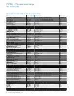
Technical data
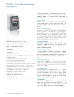
Major possible settings and the displayed text and the set default values
Description
Text on display (Eng) Values on display
Default value
Setting current for overload, locked rotor etc.
Setting I
e
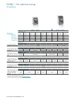
9.0 ...1207 A divided into 19 overlapping ranges.
See table, page 48
Time for start ramp
Start Ramp
1 ... 30 s, 1 ... 120 s (Range depends on Start Range)
10 s
Time for stop ramp
Stop Ramp
0 ... 30 s, 0 ... 120 s (Range depends on Stop Range)
0 s
Initial voltage for start ramp
Init Volt
30 ... 70 %
30 %
End voltage for stop ramp
End Volt
30 ... 70 %
30 %
Step down voltage
Step Down
30 ...100 %
100 %
Level of the current limit.
Current Lim
1.5 ... 7.0 x I
e
4.0 x I
e
Selection of Kick start
Kick Start
Yes, No
No
Level of Kick start if selected
Kick Level
50 ... 100 %
50 %
Time for Kick start if selected
Kick Time
0.1 ... 1.5 s
0.2
Selectable range for start ramp
Start Range
1 ... 30 s, 1...120 s
1 ... 30 s
Selectable range for stop ramp
Stop Range
0 ... 30 s, 0 ... 120 s
0 ... 30 s
Overload protection
Overload
No, Normal, Dual
Normal
Overload Class
OL Class
10 A, 10, 20, 30
10
Overload Class, Dual type, Start Class
OL Class S
10A, 10, 20, 30
10
Overload Class, Dual type, Run Class
OL Class R
10A, 10, 20, 30
10
Type of operation for overload protection
OL Op
Stop-M, Stop-A, Ind
Stop-M
Locked rotor protection
Locked Rotor
Yes, No
No
Trip level for locked rotor protection
Lock R Lev
0.5 ... 8.0 x I
e
4.0 x I
e
Trip time for locked rotor protection
Lock R Time
0.2 ... 10 s
1.0 s
Type of operation for locked rotor protection
Lock R Op
Stop-M, Stop-A, Ind
Stop-M
Underload protection
Underload
Yes, No
No
Trip level for Underload protection
Underl Lev
0.4 ... 0.8 x I
e
0.5 x I
e
Trip time for Underload protection
Underl Time
1 ... 30 s
10 s
Type of operation for Underload protection
Underl Op
Stop-M, Stop-A, Ind
Stop-M
Phase imbalance protection
Phase Imb
Yes, No
No
Trip level for phase imbalance protection
Ph Imb Lev
10 ... 80 %
80 %
Type of operation for phase imbalance protection
Ph Imb Op
Stop-M, Stop-A, Ind
Stop-M
High current protection
High I
Yes, No
No
Type of operation for high current protection
High I Op
Stop-M, Stop-A, Ind
Stop-M
Phase reversal protection
Phase Rev
Yes, No
No
Type of operation for phase reversal protection
Ph Rev Op
Stop-M, Stop-A, Ind
Stop-M
PTC protection
PTC
Yes, No
No
Type of operation for PTC protection
PTC Op
Stop-M, Stop-A
Stop-M
An external Bypass contactor is used
Ext ByPass
Yes, No
No
High current warning
Warn I=High
Yes, No
No
Trip level for high current warning
Wa I=H Lev
0.5 ... 5.0 x I
e
1.2 x I
e
Low current warning
Warn I=Low
Yes, No
No
Trip level for low current warning
Wa I=L Lev
0.4 ...1.0 x I
e
0.8 x I
e
Overload warning
Warn OL
Yes, No
No
Trip level for overload warning
Wa OL Lev
40 ... 99 %
90 %
Thyristor overload warning
Warn SCR OL
Yes, No
No
Type of operation for phase loss fault
Ph Loss Op
Stop-M, Stop-A
Stop-M
Type of operation for by-pass doesn’t close
BP open Op
Stop-M, Stop-A
Stop-M
Type of operation for by-pass doesn’t open
BP closed Op
Stop-M, Stop-A
Stop-M
Type of operation for fieldbus fault
FB Fault Op
Stop-M, Stop-A
Stop-M
Type of operation for frequency fault
Freq F Op
Stop-M, Stop-A
Stop-M
Type of operation for heat sink over temperature fault
HS Temp Op
Stop-M, Stop-A
Stop-M
Type of operation for thyristor short circuit fault
SCR SC Op
Stop-M, Stop-A
Stop-M
Function of programmable input In_0
In0
None, Reset, Enable, Jog, DOL, Start 2, FB-Dis
Reset
Function of programmable input In_1
In1
None, Reset, Enable, Jog, DOL, Start 3, FB-Dis
Reset
Function of programmable relay output K4
Relay K4
Run, TOR, Event
Run
Function of programmable relay output K5
Relay K5
Run, TOR, Event
TOR
Function of programmable relay output K6
Relay K6
Run, TOR, Event
Event
Control of the softstarter with fieldbus
Fieldb Ctrl
Yes, No
No
Number of sequences for sequence start.
No of Seq
No, 2, 3
No
Language to use on display
Language
US/UK, FI, SE, PT, NL, IT, FR, ES, DE, CN, RU, TR, PL, CZ
US/UK
Password for display
Password
No, 1 ... 255
Start mode
Start Mode
Volt, Torque
Volt
Stop mode
Stop Mode
Volt, Torque
Volt
Torque limit
Torque limit
20 ... 200 %
150 %
Analog output
Analogue Out
Yes, No
No
Analog output, reference
Anl Ref
0 ...10 V, 0 ... 20 mA, 4 ... 20 mA
4 ...20 mA
Analog output, type of value
Anl Type
I Amp, U Volt, P kW, P hp, Q kVAr, S kVA, TmpMot, TmpSCR, cosPhi
I Amp

