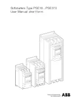
Softstarters Type PSE18...PSE370 User Manual short form 1SFC132059M9901 9
EN
13
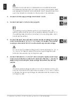
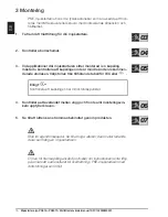
7. Switch ON the control supply voltage, terminals 1 and 2.
8.
Continue to configure parameters as described in chapter 6, Settings.
9. Switch ON the operational voltage.
There is some flexibility in the connecting of your softstarter, but fol
-
lowing the steps above will enable operation of the PSE softstarter. An
example of a complete installation can be found in the graphics section.
The first one uses fuses and contactors and the second one uses a
circuit breaker.
Depending on the two phase control, a connected motor terminal
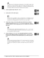
always carries live hazardous voltage. Do not touch terminals when
voltage is applied. Output terminals will have live voltage even when the
device is OFF. This can cause death or serious injury.
Summary of Contents for PSE18
Page 148: ...148 AR ...
Page 149: ...149 AR 01 02 ...
Page 150: ...150 AR 03 04 05 06 07 ...
Page 151: ...151 AR 08 08 1SFC132265F0001 PSE 1SFC132263F0001 PSE 08 08 ...
Page 152: ...152 AR 09 12 11 10 ...
Page 153: ...153 AR 13 ...
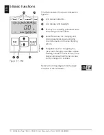
Page 154: ...154 AR 14 1SFC132235F0001 Ready Run Exit Select Reset Protection Fault A B C D E A B C D E ...
Page 155: ...155 AR 15 15 A B C D ...
Page 156: ...156 AR 16 ...
Page 157: ...157 AR 1 2 3 4 5 6 1 1 1 2 3 4 5 6 ...
Page 158: ...158 AR ...
Page 159: ...159 AR 1 1 1 1 1 1 1 ...
Page 172: ......
Page 181: ...Softstarters Type PSE18 PSE370 User Manual short form 1SFC132059M9901 181 1SFC132240F0001 07 ...
Page 191: ...Softstarters Type PSE18 PSE370 User Manual short form 1SFC132059M9901 191 ...

