60
Human machine interface (HMI)
| Installation and commissioning manual | 1SFC132081M0201
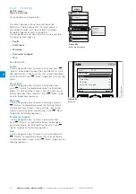
Display style
Select the display style for the home view. The selected
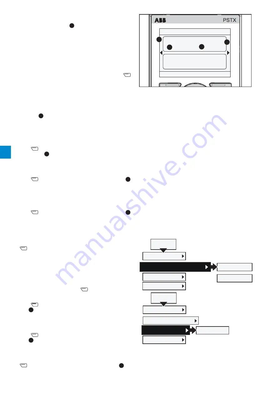
display style is shown by
2
in Figure 6.20
.
Select numeric, gauge or graph data:
• Numeric
• Gauge/bar
• Graph 15 minutes
• Graph 30 minutes
• Graph 1 hour
• Graph 24 hours
•
N/A
Use the Navigation keys to select display style, push
“Select” to set the parameter.
Display decimals
Select the amount of decimal numbers in the home view.
Use the Navigation keys to change the amount.
Push “Save” to save the value. Decimal numbers are
shown in
3
in Figure 6.20
.
Display name
You can change the name of the selected signal. The new
name can have maximum 20 characters.
Use the Navigation keys to change the characters.
Push
“Save” to save the display name. Display name
is shown by
1
in
Figure 6.20
.
Signal min
Select the minimum value in the Home view. Use the
Navigation keys to change the value.
Push
“Save” to save the value. Value is shown by
3
in
Figure 6.20
.
Signal max
Select the maximum value in the Home view. Use the
Navigation keys to change the value.
Push
“Save” to save the value. Value is shown by
3
in
Figure 6.20
.
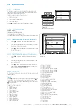
6.3.2.4
Scale value range
Use Navigation keys to mark Scale value range and push
“Select” to enable Scale value range. 3 more options
show in the display slot menu:
• Display signal min as
• Display signal max as
• Display
unit
Display signal min as
- Push
“Edit” to select
the scaled minimum value in the Home view. Use the
Navigation keys to change the value,
Push
“Save” to save the value.
See
3
in
Figure 6.20
.
Display signal max as
- Select the scaled maximum
value to show in the Home view. Use the Navigation keys
to change the value,
Push
“Save” to save the value.
See
3
in Figure 6.20
.
Display unit
- Type in the unit to show in the Home
view. You can type a unit with up to 10 characters. Use
the Navigation keys to change the characters. Push
“Save” to save the Home view unit name. See
4
in
Figure 6.20
.
Figure 6.20
Display slot
1SFC132081M0201
Local
PSTX
Motor current
A
0.0
Motor voltage
V
0.0
Options
12:00
Menu
1
4
3
2
6.3.3
Active faults/protections and
warnings
Path in menu:
Options
X
Active faults / protections
Options
X
Active warnings
You can find
active faults/protections/warnings
in the
Options menu. The menus contain information about
faults and warnings that occurred during operation, and
what protections are active.
Active faults/protections and warnings menus are
highlighted black when a fault protection or warning
occurred.
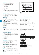
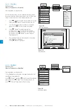
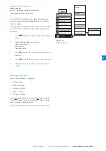
For navigation see Figure 6.21
.
For more information about fault/warnings/protections,
see chapter
10 Troubleshooting.
Faults
Protections
Options
Edit home view
Active faults / protections
Active warnings
Configure HMI
Options
Warnings
Edit home view
Active faults / protections
Active warnings
Configure HMI
Figure 6.21
Active fault/warnings/protections navigation
6
Summary of Contents for PSTX Series
Page 1: ...1SFC132081M0201 Softstarters Type PSTX30 PSTX1250 Installation and commissioning manual...
Page 4: ......
Page 6: ......
Page 10: ...10 Introduction Installation and commissioning manual 1SFC132081M0201 1...
Page 16: ...16 Quick start Installation and commissioning manual 1SFC132081M0201 2...
Page 29: ...1SFC132081M0201 Installation and commissioning manual Description 29 3...
Page 30: ...30 Description Installation and commissioning manual 1SFC132081M0201 3...
Page 36: ...36 Installation Installation and commissioning manual 1SFC132081M0201 4...
Page 50: ...50 Connection Installation and commissioning manual 1SFC132081M0201 6...
Page 72: ...72 Human machine interface HMI Installation and commissioning manual 1SFC132081M0201 6...
Page 143: ...1SFC132081M0201 Installation and commissioning manual Functions 143 7...
Page 144: ...144 Functions Installation and commissioning manual 1SFC132081M0201 7...
Page 148: ...148 Communication Installation and commissioning manual 1SFC132081M0201 8...
Page 156: ...156 Maintenance Installation and commissioning manual 1SFC132081M0201 9...
Page 168: ...168 Troubleshooting Installation and commissioning manual 1SFC132081M0201 10...
Page 176: ...176 Wiring and application diagrams Installation and commissioning manual 1SFC132081M0201 11...
Page 181: ...1SFC132081M0201 Installation and commissioning manual Third party licenses 181 12...
Page 183: ...1SFC132081M0201 Installation and commissioning manual Revision 183 13...
Page 187: ...1SFC132081M0201 Installation and commissioning manual Index 187 14...


