Operation Manual / Power2 845-M / High-pressure stage
Figures
© Copyright 2022 ABB. All rights reserved.
HZTL4069_EN
Revision F
March 2022
Figures
Fig. 1: Power2 layout and function............................... 7
Fig. 3: Power2 HP diagram ........................................... 9
nhibitor (VCI)................... 12
Fig. 5: Package with hygrometer................................ 13
Fig. 6: Locations of Power2 HP warning plates....... 18
Fig. 7: Rating plate ........................................................ 19
Fig. 8: Location of Power2 HP rating plate ............. 20
Fig. 9: Attachment of loads on the crane hook ....... 21
Fig. 10: Attachment angle............................................ 21
Fig. 11: Swivel lifting eye (example) .......................... 30
Fig. 12: Suspension of complete high-pressure stage
31
Fig. 13: Suspension of complete high-pressure stage
32
Fig. 14: Lubricating oil pressure measuring point. 38
Fig. 15: Functional principle........................................ 40
Fig. 16: Dimension X..................................................... 42
Fig. 17: Removing the speed measurement system....
42
Fig. 18: Setting dimension X....................................... 43
Fig. 19: Control dimension S ...................................... 44
Fig. 20: Load/time chart ............................................. 56
Fig. 21: Overview of assemblies................................. 68
Fig. 22: Removing the air suction branch ................ 69
Fig. 23: Removing wall insert 1................................... 70
Fig. 24: Removing wall insert 2 .................................. 70
Fig. 25: Removing wall insert 3 ................................... 71
Fig. 26: Removing the compressor casing ............... 72
Fig. 27: Moving out cartridge group 1 ....................... 73
Fig. 28: Moving out cartridge group 2....................... 73
Fig. 29: Moving out cartridge group 3...................... 74
Fig. 30: Moving out cartridge group 4 ..................... 74
Fig. 31: Removing the nozzle ring............................... 75
Fig. 32: Measuring axial clearance A........................... 76
Fig. 33: Installing the nozzle ring ................................ 77
Fig. 34: Installing O-rings ............................................. 78
Fig. 35: Installing the cartridge group 1 .................... 78
Fig. 36: Installing the cartridge group 2.................... 79
Fig. 37: Control dimension X........................................ 80
Fig. 38: Installing the compressor casing................. 81
Fig. 39: Installing the wall insert 1 .............................. 82
Fig. 40: Installing the wall insert 2.............................. 83
Fig. 41: Installing the air suction branch ................... 84
Fig. 42: Tightening torques ......................................... 85
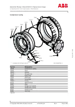
Fig. 43: Cover plate / gasket and sleeves ................. 87
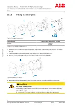
Fig. 44: Fitting the cover plate.................................... 88
Fig. 45: Installing the casing........................................ 88
Page
102
/
104
Page
102
/
104
Summary of Contents for PT004116
Page 2: ......


