8.2 Grounding
The breaker cabinet includes a standard NEMA 2 hole drilled stainless steel pad on the rear
for grounding. Any voltage transformers used should be grounded to the main ground wire
leading from the breaker to ground.
To ground the control cabinet, use the connector provided which accepts a #6 - 2/0 AWG
conductor. Ground the control cabinet to the main ground wire from this external connector.
All ground wire used must be #6 AWG minimum.
8.3 Arrester Protection
ABB recommends that surge arresters be properly applied in the substation.
8.4 Control Power
Supply the control power as indicated on the wiring diagram. If 240 VAC is used, verify the
connections for the heaters before applying power.
For breakers not equipped with DIN-Rail style connectors, check all terminal block
connections for proper tightness.
For details of the overall control circuit refer to the specific wiring diagrams supplied with the
breaker.
8.5 Final Inspection
When the breaker has been installed and all mechanical and electrical connections
completed, EXCEPT ENERGIZING THE POWER LINE, the following points of inspection are
recommended:
1. Ensure the breaker is properly leveled and securely anchored.
2. Make a final check of tightness of all hardware.
3. Check that the heaters work.
4. Securely tighten terminal and ground connections.
5. Check control cable entrance fittings for tightness.
6. Operate the breaker from the control box to verify normal operation.
7. Secure all doors and ensure proper gasketing for weather.
8. Ensure that all tools are removed.
Page 7
38-929M-15A 10/15/02 1:11 PM Page 11
Summary of Contents for R-MAG Series
Page 2: ...38 929M 15A 10 15 02 1 11 PM Page 2 ...
Page 4: ...38 929M 15A 10 15 02 1 11 PM Page 4 ...
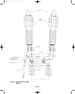
Page 15: ...Page 11 Figure 3 Interrupter Assembly 1200 A 38 929M 15A 10 15 02 1 11 PM Page 15 ...
Page 16: ...Page 12 Figure 4 Interrupter Assembly 2000 A 38 929M 15A 10 15 02 1 11 PM Page 16 ...
Page 17: ...Page 13 Figure 5 Interrupter Assembly 3000 A 38 929M 15A 10 15 02 1 11 PM Page 17 ...
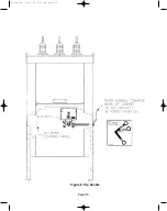
Page 20: ...Figure 8 Trip Handle Page 16 38 929M 15A 10 15 02 1 11 PM Page 20 ...
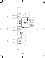
Page 21: ...Figure 9 High Voltage Cabinet Layout Page 17 38 929M 15A 10 15 02 1 11 PM Page 21 ...
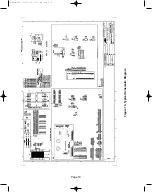
Page 22: ...Figure 10 Typical Schematic Diagram Page 18 38 929M 15A 10 15 02 1 11 PM Page 22 ...
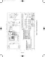
Page 23: ...Figure 11 Typical Connecting Diagram Page 19 38 929M 15A 10 15 02 1 11 PM Page 23 ...
Page 24: ...Figure 12 Typical Outline 1200 A Page 20 38 929M 15A 10 15 02 1 11 PM Page 24 ...
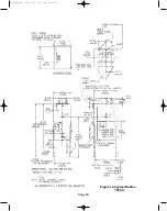
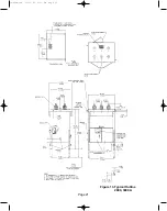
Page 25: ...Figure 13 Typical Outline 2000 3000 A Page 21 38 929M 15A 10 15 02 1 11 PM Page 25 ...
Page 30: ...Page 26 38 929M 15A 10 15 02 1 11 PM Page 30 ...
Page 44: ...Page 40 ILLUSTRATION 8 READY LED OFF 38 929M 15A 10 15 02 1 11 PM Page 44 ...
Page 45: ...Page 41 ILLUSTRATION 9 CB WILL EITHER NOT OPEN OR CLOSE 38 929M 15A 10 15 02 1 11 PM Page 45 ...


