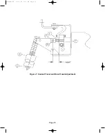
9.2 Contact Travel and Over-Travel Adjustment (See Figure 7)
With the breaker in the open position:
1. Loosen Locknut (F) on Bolt Stem (E).
2. Remove Pin (B) while applying pressure from the back of the Contact Block. Allow
Contact Block to move slowly to closed position. Caution: finger pinch point.
3. Loosen Pullrod Locknut (D).
4. Turn Pullrod until center of hole for Pin (B) is 1.687” from Contact Block (C). (This step
sets a reference point for the Bell Cranks.)
5. Spin Bolt Stem (E) until Pin (B) can be inserted and then remove Pin (B). (This step
establishes a reference from VI Contact to the bell cranks.)
6. Spin Bolt Stem (E) 6-6.5 full turns (6.5 turns is preferred final travel, but 6 acceptable
prior to contact conditioning) CW. (This step sets the Contact Travel.)
7. Pull from back of Contact Block (C) until Pin (B) can be inserted.
8. Install new X-washer and tighten all hardware. Do not reuse washers.
9. Measure Travel and Over-Travel by opening and closing breaker. Confirm breaker is
within limits. Minor adjustments can be made by turning pushrod (A).
10. Over-Travel Limits (Gap produced at top of Pullrod while closed) are MIN 0.17”, MAX
0.260”.
11. Travel Limits (Difference in measurements between Contact Block in open and closed
position) are 10.5 mm - 12.5 mm (0.413”-0.492”).
Operate breaker a minimum of 200 times to season new contacts, readjust breaker (Step 9).
Page 10
38-929M-15A 10/15/02 1:11 PM Page 14
Summary of Contents for R-MAG Series
Page 2: ...38 929M 15A 10 15 02 1 11 PM Page 2 ...
Page 4: ...38 929M 15A 10 15 02 1 11 PM Page 4 ...
Page 15: ...Page 11 Figure 3 Interrupter Assembly 1200 A 38 929M 15A 10 15 02 1 11 PM Page 15 ...
Page 16: ...Page 12 Figure 4 Interrupter Assembly 2000 A 38 929M 15A 10 15 02 1 11 PM Page 16 ...
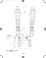
Page 17: ...Page 13 Figure 5 Interrupter Assembly 3000 A 38 929M 15A 10 15 02 1 11 PM Page 17 ...
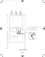
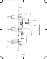
Page 20: ...Figure 8 Trip Handle Page 16 38 929M 15A 10 15 02 1 11 PM Page 20 ...
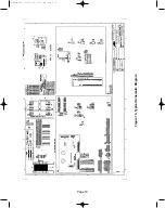
Page 21: ...Figure 9 High Voltage Cabinet Layout Page 17 38 929M 15A 10 15 02 1 11 PM Page 21 ...
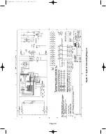
Page 22: ...Figure 10 Typical Schematic Diagram Page 18 38 929M 15A 10 15 02 1 11 PM Page 22 ...
Page 23: ...Figure 11 Typical Connecting Diagram Page 19 38 929M 15A 10 15 02 1 11 PM Page 23 ...
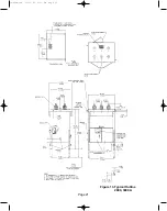
Page 24: ...Figure 12 Typical Outline 1200 A Page 20 38 929M 15A 10 15 02 1 11 PM Page 24 ...
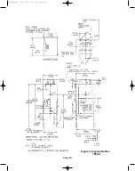
Page 25: ...Figure 13 Typical Outline 2000 3000 A Page 21 38 929M 15A 10 15 02 1 11 PM Page 25 ...
Page 30: ...Page 26 38 929M 15A 10 15 02 1 11 PM Page 30 ...
Page 44: ...Page 40 ILLUSTRATION 8 READY LED OFF 38 929M 15A 10 15 02 1 11 PM Page 44 ...
Page 45: ...Page 41 ILLUSTRATION 9 CB WILL EITHER NOT OPEN OR CLOSE 38 929M 15A 10 15 02 1 11 PM Page 45 ...


