background image

38-929M-15A  10/15/02  1:11 PM  Page 2

Summary of Contents for R-MAG Series

Page 1: ...Instructions for Vacuum Circuit Breaker Type ABB R MAG OVB DCM 15 5 kV 1250 2000 3000 A 38 929M 15A ...

Page 2: ...38 929M 15A 10 15 02 1 11 PM Page 2 ...

Page 3: ...RATIONS Description Page Figure 1 Hazardous Voltage Nameplate 1 Figure 2 Lifting Detail 3 Figure 3 Interrupter Assembly 1200 A 11 Figure 4 Interrupter Assembly 2000 A 12 Figure 5 Interrupter Assembly 3000 A 13 Figure 6 Contact Erosion Graph 15 kV 14 Figure 7 Contact Travel and Over Travel Adjustment 15 Figure 8 Trip Handle 16 Figure 9 High Voltage Cabinet Layout 17 Figure 10 Typical Schematic Diag...

Page 4: ...38 929M 15A 10 15 02 1 11 PM Page 4 ...

Page 5: ...inciples and service operations are not included It is important to note that this document contains some warnings and cautions against some specific service methods which could cause personal injury to service personnel or could damage equipment or render it unsafe Please understand that these warnings could not cover all conceivable ways in which service whether or not recommended by ABB might b...

Page 6: ...nspection report File a formal claim with the carrier supported with paid freight bill inspection report and invoice The local ABB Sales Office must be notified Normally this must be done within 10 days of receipt or receiver assumes all responsibility for damage 3 1 Receiving Inspection Upon receipt it is important to inspect promptly to be certain that the correct material has been received In c...

Page 7: ...od 4 2 Housing The doors of the breaker housing are removable and are retained by four pins The position indicator is visible through the front door The breaker nameplate showing rating information serial number and shop order number are mounted on the right hand side of the housing 4 3 Phase Assembly Figure 3 shows the details of the phase assembly The back bus work is attached directly to the fi...

Page 8: ...eadings are made on each phase of the breaker using a Biddle Ductor Typical values do not exceed 150 micro ohms 5 Voltage Withstand The complete breaker is tested a between live parts and tank b across open contacts and c between phases In compliance with ANSI C37 09 IEC an AC dielectric withstand test at 50 kV is performed Test duration is one minute 6 Wiring Insulation The terminal block connect...

Page 9: ...over plate If the panel is green the breaker is open and if the panel is red the breaker is closed To perform a close or open ensure the Ready light is illuminated above the Close 1 and Open 0 buttons Press the appropriate button firmly keeping hands and loose clothing clear of operating linkages Nothing will happen if the open button is pressed if the breaker is already open and conversely for cl...

Page 10: ...one minute Do not exceed 37 5 kVAC 4 If internal flashover occurs isolate the phases and test each one independently to identify the defective interrupter Any defective interrupter must be replaced prior to the breaker being placed in service 8 0 INSTALLATION It is required that the breaker be vertical and level and securely fastened Follow your company guidelines and various codes for setting the...

Page 11: ...plying power For breakers not equipped with DIN Rail style connectors check all terminal block connections for proper tightness For details of the overall control circuit refer to the specific wiring diagrams supplied with the breaker 8 5 Final Inspection When the breaker has been installed and all mechanical and electrical connections completed EXCEPT ENERGIZING THE POWER LINE the following point...

Page 12: ...ssure is maintained in the closed position Contact erosion reduces the compression of the over travel spring which in turn increases the contact travel Total travel of the actuator is fixed See 9 2 steps 9 11 for minor adjustments Contact wear can be visually inspected A line is scribed on the moving contact stem 0 08 from VI end guide When the line reaches the VI end guide replace vacuum interrup...

Page 13: ... Hex nut remains in position 5 Wedge large screwdriver tip to spread gap on the Contact Block This will allow the threaded moving end of the VI to easily spin out of the Contact Block in step 7 6 Remove bus at fixed end of the VI 7 Rotate VI counterclockwise CCW until it is completely free of the Contact Block 8 Install new VI carefully ensuring the VI spins in to the Contact Block without any res...

Page 14: ...6 Spin Bolt Stem E 6 6 5 full turns 6 5 turns is preferred final travel but 6 acceptable prior to contact conditioning CW This step sets the Contact Travel 7 Pull from back of Contact Block C until Pin B can be inserted 8 Install new X washer and tighten all hardware Do not reuse washers 9 Measure Travel and Over Travel by opening and closing breaker Confirm breaker is within limits Minor adjustme...

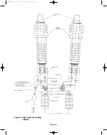
Page 15: ...Page 11 Figure 3 Interrupter Assembly 1200 A 38 929M 15A 10 15 02 1 11 PM Page 15 ...

Page 16: ...Page 12 Figure 4 Interrupter Assembly 2000 A 38 929M 15A 10 15 02 1 11 PM Page 16 ...

Page 17: ...Page 13 Figure 5 Interrupter Assembly 3000 A 38 929M 15A 10 15 02 1 11 PM Page 17 ...

Page 18: ...14 Figure 6 Contact Erosion Graph Permissible number of vacuum interrupter operating cycles n as a function of the breaking current la for 15 kV R MAG Vacuum Interrupter 38 929M 15A 10 15 02 1 11 PM Page 18 ...

Page 19: ...Figure 7 Contact Travel and Over Travel Adjustment Page 15 1 687 38 929M 15A 10 15 02 1 11 PM Page 19 ...

Page 20: ...Figure 8 Trip Handle Page 16 38 929M 15A 10 15 02 1 11 PM Page 20 ...

Page 21: ...Figure 9 High Voltage Cabinet Layout Page 17 38 929M 15A 10 15 02 1 11 PM Page 21 ...

Page 22: ...Figure 10 Typical Schematic Diagram Page 18 38 929M 15A 10 15 02 1 11 PM Page 22 ...

Page 23: ...Figure 11 Typical Connecting Diagram Page 19 38 929M 15A 10 15 02 1 11 PM Page 23 ...

Page 24: ...Figure 12 Typical Outline 1200 A Page 20 38 929M 15A 10 15 02 1 11 PM Page 24 ...

Page 25: ...Figure 13 Typical Outline 2000 3000 A Page 21 38 929M 15A 10 15 02 1 11 PM Page 25 ...

Page 26: ...urrent Loop Peak 32 5 kA 65 kA Transient Recovery Voltage 29 kV Peak time to peak is 36 µsec Load Current Switching Capability 1250 A Rated Line Charging Breaking Current 100 A Rated Cable Charging Breaking Current 400 A Rated Isolated Capacitor Bank Breaking 400 A Definite Purpose Rated Back to Back Capacitor Bank Breaking 400 A Definite Purpose Rated Capacitor Bank Inrush Making 20 kA Rated Capa...

Page 27: ...RMINAL RATIO OHMS 25 C X2 X3 50 5 015 X2 X3 100 5 052 X1 X2 100 5 029 X1 X1 200 5 104 X1 X3 150 5 044 X1 X3 300 5 156 X4 X5 200 5 058 X4 X5 400 5 208 X3 X4 250 5 073 X3 X4 500 5 260 X2 X4 300 5 088 X2 X4 600 5 312 X1 X4 400 5 117 X1 X4 800 5 416 X3 X5 450 5 131 X3 X5 900 5 468 X2 X5 500 5 146 X2 X5 1000 5 520 X1 X5 600 5 175 X1 X5 1200 5 624 VOLTS NON INDUCTIVE CIRCUITS INDUCTIVE CIRCUITS CONTINUO...

Page 28: ...VOLTS 20 4 VOLTS TO 264 VOLTS KM1005 OPENING COMMANDS CAN OPENING COMMANDS CAN INCLUDES TRIP GO AS LOW AS 16 8 VAC GO AS LOW AS 16 8 VAC AND CLOSE BINARY INPUTS DC 20 4 VOLTS TO 264 VOLTS 20 4 VOLTS TO 264 VOLTS KM1005 OPENING COMMANDS CAN OPENING COMMANDS CAN INCLUDES TRIP GO AS LOW AS 16 8 VDC GO AS LOW AS 16 8 VDC AND CLOSE AUXILIARY POWER 20 4 VOLTS TO 52 8 VOLTS 85 VOLTS TO 264 VOLTS AC KM100...

Page 29: ...ED2 0 Control Assembly HV LV 1B09551 608 607 Electrolytic Capacitor 100V Assembly 12A01272G01 ED2 0 Board HV LV 751010 810 809 Renewal parts available from ABB exclusively Contact your local ABB office Page 25 Figure 14 Breaker Nameplate 11 0 RENEWAL PARTS 38 929M 15A 10 15 02 1 11 PM Page 29 ...

Page 30: ...Page 26 38 929M 15A 10 15 02 1 11 PM Page 30 ...

Page 31: ...APPENDIX A INSTALLATION MAINTENANCE INSTRUCTIONS R MAG Medium Voltage Vacuum Power Circuit Breaker ED2 0 MAGNETIC ACTUATOR CONTROL BOARD Page 27 38 929M 15A 10 15 02 1 11 PM Page 31 ...

Page 32: ...otection Trip KM1005 Pins 7 8 33 4 6 Second Trip KM1005 Pins 7 8 33 4 7 Circuit Breaker Locked Open KM1005 Pins 11 12 33 4 8 Under Voltage Trip KM1005 Pins 13 and 14 33 5 0 BINARY OUTPUTS 34 5 1 Circuit Breaker Opened KM1004 Pins 1 2 34 5 2 Circuit Breaker Closed KM1004 Pins 3 4 34 5 3 Circuit Breaker Auxiliary Opened KM1004 Pins 5 6 34 5 4 Circuit Breaker Auxiliary Closed KM1004 Pins 7 8 34 5 5 U...

Page 33: ...d a pulse width of 45 milliseconds for opening operations and 60 milliseconds for closing operations The ED2 0 board also provides access through KM1003 for external charging and discharging of the Storage Unit capacitors A 10 kOhm capacitor discharge resistor is mounted on the circuit board Discharging is done by jumpering KM1003 pins 5 and 6 The time constant is 33 minutes An external resistor c...

Page 34: ...ONIC DRIVE BOARD FEATURES ILLUSTRATION 2 MAIN ED2 0 BOARD FEATURES Page 30 FEATURE BINARY INPUTS 6 FAST SLOW INPUT FAST OR SLOW BINARY OUTPUTS 7 WRONG POSITION AUTO TRIP YES CAPACITOR VOLTAGE MONITOR YES COIL CONTINUITY MONITOR YES PROTECTION TRIP INPUT YES SAFE OPEN YES UNDER VOLTAGE AUTO TRIP YES ENERGY FAIL AUTO TRIP YES AUXILIARY CAPACITOR CHARGE DISCHARGE YES OUTPUT POWER REDUCTION 33 W YES J...

Page 35: ...idered valid The Fast Input only requires the input to be active for 2 milliseconds before the signal is considered valid However this makes the Fast Input feature more prone to noise 3 4 ACTUATOR CLOSE AND TRIP COIL CONTINUITY MONITOR See Illustration 10 Troubleshooting Guide 3 5 WRONG POSITION AUTO TRIP An Auto Trip command will be issued in the event the breaker does not perform a successful cl...

Page 36: ...w threshold at about 18 VDC and 19 VAC with the exception of the Protection Relay input which has a low threshold of about 7 VDC To avoid false triggering by noise the inputs must be active for at least 10 milliseconds A Fast Input mode is available so that the input can be selected after only 2 milliseconds Choosing the Fast Input mode may make the board more sensitive to nuisance opening or clos...

Page 37: ...ed to as Shunt Trip It functions the same as the Remote Input with the exception of the input impedance which is 300 kOhms 4 7 CIRCUIT BREAKER LOCKED OPEN KM1005 Pins 11 and 12 The Circuit Breaker Locked Open feature functions like the familiar 69 switch The circuit is activated when the external trip handle is moved from its normal position i e in the trip position In this position the breaker ca...

Page 38: ...nd 4 The Circuit Breaker Closed contacts are normally open They close only when the circuit breaker is in the Closed position 5 3 CIRCUIT BREAKER AUXILIARY OPEN KM1004 Pins 5 and 6 The Circuit Breaker Auxiliary Open contacts which close whenever the breaker is in the Open position 5 4 CIRCUIT BREAKER AUXILIARY CLOSED KM1004 Pins 7 and 8 Additional set of normally open contacts which close whenever...

Page 39: ... VDC 1 A Maximum Capacitance 1 5 pF TIMING CHARACTERISTICS Maximum Actuating Time 5 0 milliseconds Maximum Releasing Time 3 0 milliseconds INSULATION Between Contacts and Coil 4000 Vrms 50 Hz 1 min Between Open Contact 1000 Vrms 50 Hz 1 min Resistance Roff 1000 Megohms at 500 VDC ENVIRONMENTAL CHARACTERISTICS Operating Temperature Range 40 to 85 Degrees C Storing Temperature Range 40 to 100 Degree...

Page 40: ...hresholds must be reached to complete the specified operations 1 The capacitor voltage threshold for an Open operation is 49 volts 2 The capacitor voltage threshold for a Close Open operation is 72 5 volts 3 The capacitor voltage threshold for a Open Close Open operation is 78 volts Illustrations 5 and 6 are provided to indicate the states of the Ready LED Ready and Not Ready output contacts Page ...

Page 41: ...TOR LIFE The 0 1 Farad Electrolytic capacitors are designed to be operated in the temperature range of 40 F to 185 F The End of Life corresponds to the point at which the capacitance decreases by 20 or more It is recommended that replacement of capacitors be performed every 15 years for tropical climates and 20 years for an average yearly temperature in the outdoor breaker enclosure of less than 1...

Page 42: ...r Ready LED blinking Ready LED off O operations Ready contact closed Ready contact opened Not ready contact opened Not ready contact closed Capacitor Energy insufficient for Ready LED off Ready LED off any operations Ready contact opened Ready contact opened Not ready contact closed Not ready contact closed Close Coil continuity not right Ready LED blinking Ready LED off Ready contact closed Ready...

Page 43: ...7 0 TROUBLESHOOTING FLOWCHARTS ILLUSTRATION 7 READY LED CONTINUALLY FLASHING Page 39 38 929M 15A 10 15 02 1 11 PM Page 43 ...

Page 44: ...Page 40 ILLUSTRATION 8 READY LED OFF 38 929M 15A 10 15 02 1 11 PM Page 44 ...

Page 45: ...Page 41 ILLUSTRATION 9 CB WILL EITHER NOT OPEN OR CLOSE 38 929M 15A 10 15 02 1 11 PM Page 45 ...

Page 46: ...coil is disconnected or operation is available open the broken CB the Ready LED will be turned off and check the closing coil circuit The auxiliary supply voltage has If the CB is closed you can been turned off perform a CO operation connect the auxiliary supply During the Start up or after the Wait a few seconds operations the capacitor bank is charging The closing The Closing Coil is broken or d...

Page 47: ...The close position sensor is not connected Verify the close position sensor and then opens or broken circuit during a close The CB doesn t reach the correct close Verify the presence of unwanted operation position objects under the Magnetic Actuator Plunger The CB opens if the The UV function is active and Either disable the UV auxiliary supply is the auxiliary supply is parallel to this input fun...

Page 48: ...Page 44 ILLUSTRATION 12 ED2 0 CIRCUIT BOARD AND CONNECTIONS 8 0 STANDARD ED2 0 CIRCUIT BOARD AND CONNECTING DIAGRAM 38 929M 15A 10 15 02 1 11 PM Page 48 ...

Page 49: ...ILLUSTRATION 13 ED2 0 CIRCUIT BOARD CONNECTORS Page 45 3 2 1 O N 3 2 1 O N O N 4 5 3 2 1 4 3 2 1 38 929M 15A 10 15 02 1 11 PM Page 49 ...

Page 50: ...C GROUND 0 VDC KM1001 6 ELECTRONIC GROUND 0 VDC KM1002 1 CAPACITOR PLUS 80 VDC KM1002 2 CAPACITOR PLUS 80 VDC KM1002 3 CAPACITOR MINUS 0 VDC KM1002 4 CAPACITOR MINUS 0 VDC KM1002 5 CLOSE COIL 80 VDC KM1002 6 CLOSE COIL 80 VDC KM1002 7 TRIP COIL 80 VDC KM1002 8 TRIP COIL 80 VDC KM1002 9 CLOSE COIL KM1002 10 CLOSE COIL KM1002 11 TRIP COIL KM1002 12 TRIP COIL Page 46 38 929M 15A 10 15 02 1 11 PM Page...

Page 51: ...10 Ohm 25 watt resistor can be jumpered directly across any one of the capacitors KM1004 GENERAL PURPOSE BINARY OUTPUT CONTACTS KM1003 1 NOT USED KM1003 2 AUXILIARY SUPPLY KM1003 3 AUXILIARY SUPPLY KM1003 4 V CAPACITOR KM1003 5 V CAP 10 kOhm RESISTOR KM1003 6 V CAPACITOR OUTPUT NUMBER OUTPUT NAME KM1004 PIN NUMBERS N 1 CB OPENED 1 2 N 2 CB CLOSED 3 4 N 3 CB OPENED BY AUX 5 6 TRIP SIGNAL N 4 CB CLO...

Page 52: ...use only KM1009 RS232 DOWNLOAD INTERFACE For ABB use only KM1010 ANALOG BOARD VERSUS MOTHER BOARD Future design INPUT NUMBER INPUT NAME KM1005 PIN NUMBERS N 1 CLOSE 1 2 N 2 OPEN 3 4 N 3 AUXILIARY SAFE OPEN 5 6 N 4 SECOND OPENING 7 8 PROTECTION RELAY TRIP N 5 NOT USED 9 10 N 6 CB OPEN LOCKED 69 11 12 N 7 UNDER VOLTAGE INPUT 13 14 Page 48 38 929M 15A 10 15 02 1 11 PM Page 52 ...

Page 53: ... with I1004 and also selecting an appropriate range with I1001 DIP SWITCH I1005 FUTURE USE ONLY JUMPER JP1001 Sets input number 4 to either normal pins 2 to 3 or as a protection input pins 1 to 2 JUMPER JP1005 ABB USE ONLY JUMPER J1001 Used to reduce the ED2 0 board power consumption from 75 to 33 watts Capacitor charging time will increase in the 33 watt setting SWITCH POSITION OFF ON 1 INPUT 1 F...

Page 54: ...pendix A for Switch and Jumper locations The following represents the functional Jumper and Dip Switch settings which are the shipped configuration Jumper JP1001 Auxiliary Protection Relay Input Pins 2 to 3 Dip Switch I1001 Under Voltage Range Position 1 ON Position 2 ON Position 3 ON Dip Switch I1002 Fast Slow Input Position 4 sets Input 3 as Auxiliary or Safe input Position 1 ON Position 2 ON Po...

Page 55: ...38 929M 15A 10 15 02 1 11 PM Page 55 ...

Page 56: ...ABB Inc 655 Century Point Lake Mary FL 32746 Tel 1 407 732 2000 1 800 929 7947 Fax 407 732 2132 www abb com mediumvoltage ISO 9001 Certified IB 38 929M 15 A World Arts 10 02 ...

Reviews: