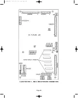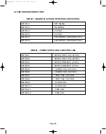
3.1 CIRCUIT BREAKER OPEN LOCK (69 SWITCH)
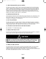
The Open Lock feature is used for service to prevent the breaker from being closed (either
locally or remotely) during maintenance. The pin locations for this binary input are KM1004
pins 11 and 12. When the circuit breaker is tripped, by operating the manual trip handle, the
breaker will go into the Open Lock mode. This prevents any future closings until the Trip
Handle is returned to the Normal Position. The Manual Trip Handle must be left in the down
position for the switch to remain open (i.e., locked open).
3.2 TEMPERATURE PROTECTION
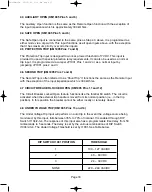
The Temperature Protection circuit monitors the average temperature of a critical area on the
ED2.0 power supply. The output power will be linearly reduced to zero as the temperature
increases from 78 degrees C to 95 degrees C.
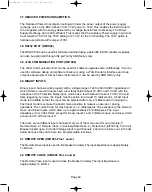
3.3 FAST VS SLOW INPUTS
The Slow Input needs to be active at least 10 milliseconds before the signal is considered
valid. The Fast Input only requires the input to be active for 2 milliseconds before the signal is
considered valid. However, this makes the Fast Input feature more prone to noise.
3.4 ACTUATOR CLOSE AND TRIP COIL CONTINUITY MONITOR
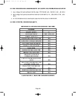
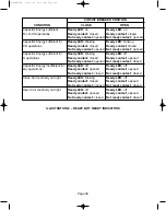
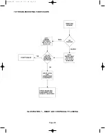
See Illustration 10 - Troubleshooting Guide.
3.5 WRONG POSITION AUTO TRIP
An Auto Trip command will be issued in the event the breaker does not perform a successful
close operation within 95 milliseconds after the close command is issued.
3.6 ENERGY FAILURE AUTO TRIP
The Energy Failure Auto Trip function is selected by Dip Switch I1004-1 and will cause the
breaker to auto trip in the event the capacitor voltage falls below 49 volts. Necessary
precautions must be taken when power is removed (e.g., power removed for maintenance) as
the breaker will automatically trip if I1004-1 is in the “On” position.
Page 31
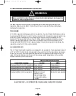
CAUTION
If power is removed from unit, and the Dip Switch I1004-1 is placed in the “on”
position, the breaker will automatically trip in approximately 3 minutes. Make
sure personnel and tools are clear from breaker. See Section 3.6 below.
38-929M-15A 10/15/02 1:11 PM Page 35
Summary of Contents for R-MAG Series
Page 2: ...38 929M 15A 10 15 02 1 11 PM Page 2 ...
Page 4: ...38 929M 15A 10 15 02 1 11 PM Page 4 ...
Page 15: ...Page 11 Figure 3 Interrupter Assembly 1200 A 38 929M 15A 10 15 02 1 11 PM Page 15 ...
Page 16: ...Page 12 Figure 4 Interrupter Assembly 2000 A 38 929M 15A 10 15 02 1 11 PM Page 16 ...
Page 17: ...Page 13 Figure 5 Interrupter Assembly 3000 A 38 929M 15A 10 15 02 1 11 PM Page 17 ...
Page 20: ...Figure 8 Trip Handle Page 16 38 929M 15A 10 15 02 1 11 PM Page 20 ...
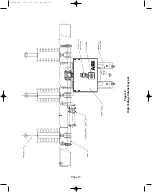
Page 21: ...Figure 9 High Voltage Cabinet Layout Page 17 38 929M 15A 10 15 02 1 11 PM Page 21 ...
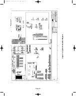
Page 22: ...Figure 10 Typical Schematic Diagram Page 18 38 929M 15A 10 15 02 1 11 PM Page 22 ...
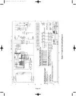
Page 23: ...Figure 11 Typical Connecting Diagram Page 19 38 929M 15A 10 15 02 1 11 PM Page 23 ...
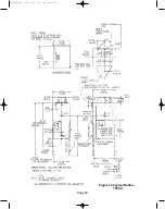
Page 24: ...Figure 12 Typical Outline 1200 A Page 20 38 929M 15A 10 15 02 1 11 PM Page 24 ...
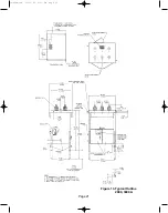
Page 25: ...Figure 13 Typical Outline 2000 3000 A Page 21 38 929M 15A 10 15 02 1 11 PM Page 25 ...
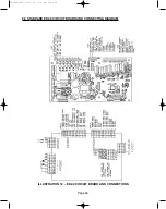
Page 30: ...Page 26 38 929M 15A 10 15 02 1 11 PM Page 30 ...
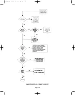
Page 44: ...Page 40 ILLUSTRATION 8 READY LED OFF 38 929M 15A 10 15 02 1 11 PM Page 44 ...
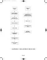
Page 45: ...Page 41 ILLUSTRATION 9 CB WILL EITHER NOT OPEN OR CLOSE 38 929M 15A 10 15 02 1 11 PM Page 45 ...

