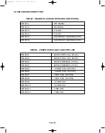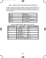
3.7 REDUCED POWER CONSUMPTION
The Reduced Power Consumption setting will lower the power output of the power supply
recharge unit, on the ED2.0 board, from 75 W power to 33 W. This enables the ED2.0 board
to be supplied with the energy delivered by a voltage transformer if necessary. The Power
Supply Recharge Unit is 80% efficient. This means that the Auxiliary Power supply input must
be at least 93.75 W for the 75 W setting or 41.3 W for the 33 W setting. The 33 W option is
hardware selectable with Jumper J1001.
3.8 RS232 PORT (KM1009)
The RS232 Port can be used for software download using a batch file in DOS window. Upgrades
can also be performed through this port but by ABB factory only.
3.9 JTAG COMMUNICATION PORT (KM1008)
The JTAG Communication Port can be used for software upgrades also. Additionally, it can be
used for software debug and software checksum using a JTAG Emulator Interface and code
compose development tool by Texas Instruments. It can be used by ABB factory only.
4.0 BINARY INPUTS
Binary input channels work properly with a voltage range of 24 to 264 VAC/DC regardless of
which board is used. All inputs have a low threshold at about 18 VDC and 19 VAC with the
exception of the Protection Relay input, which has a low threshold of about 7 VDC. To avoid
false triggering by noise, the inputs must be active for at least 10 milliseconds. A Fast Input
mode is available so that the input can be selected after only 2 milliseconds. Choosing the
Fast Input mode may make the board more sensitive to nuisance opening or closing
operations. The current draw for most inputs is < 2 milliamperes. The exception is the Remote
Open and Close inputs, which draw up to approximately 20 milliamperes. The input
impedance (Z) is 300 kOhms except for binary inputs 1 and 2 (Remote open and close) which
are around 14 kOhms input Z.
There are seven different input channels. Only six of them are used for our products: 1)
Remote Open, 2) Remote Close, 3) Auxiliary/Safe Open, 4) Protection Trip/2nd Trip, 5) Circuit
Breaker locked open, 6) Under Voltage Input. Input channels 2 and 3 are broken out in the list
below because they each have two programmable functions.
4.1 REMOTE OPEN (KM1005 Pins 1 and 2)
The Remote Open input is used to trip breaker remotely. The input impedance is approximately
14 kOhms.
4.2 REMOTE CLOSE (KM1005 Pins 3 and 4)
The Remote Close input is used to close the breaker remotely. The input impedance is
approximately 14 kOhms.
Page 32
38-929M-15A 10/15/02 1:11 PM Page 36
Summary of Contents for R-MAG Series
Page 2: ...38 929M 15A 10 15 02 1 11 PM Page 2 ...
Page 4: ...38 929M 15A 10 15 02 1 11 PM Page 4 ...
Page 15: ...Page 11 Figure 3 Interrupter Assembly 1200 A 38 929M 15A 10 15 02 1 11 PM Page 15 ...
Page 16: ...Page 12 Figure 4 Interrupter Assembly 2000 A 38 929M 15A 10 15 02 1 11 PM Page 16 ...
Page 17: ...Page 13 Figure 5 Interrupter Assembly 3000 A 38 929M 15A 10 15 02 1 11 PM Page 17 ...
Page 20: ...Figure 8 Trip Handle Page 16 38 929M 15A 10 15 02 1 11 PM Page 20 ...
Page 21: ...Figure 9 High Voltage Cabinet Layout Page 17 38 929M 15A 10 15 02 1 11 PM Page 21 ...
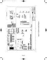
Page 22: ...Figure 10 Typical Schematic Diagram Page 18 38 929M 15A 10 15 02 1 11 PM Page 22 ...
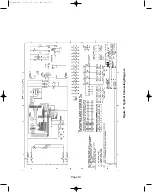
Page 23: ...Figure 11 Typical Connecting Diagram Page 19 38 929M 15A 10 15 02 1 11 PM Page 23 ...
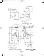
Page 24: ...Figure 12 Typical Outline 1200 A Page 20 38 929M 15A 10 15 02 1 11 PM Page 24 ...
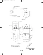
Page 25: ...Figure 13 Typical Outline 2000 3000 A Page 21 38 929M 15A 10 15 02 1 11 PM Page 25 ...
Page 30: ...Page 26 38 929M 15A 10 15 02 1 11 PM Page 30 ...
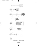
Page 44: ...Page 40 ILLUSTRATION 8 READY LED OFF 38 929M 15A 10 15 02 1 11 PM Page 44 ...
Page 45: ...Page 41 ILLUSTRATION 9 CB WILL EITHER NOT OPEN OR CLOSE 38 929M 15A 10 15 02 1 11 PM Page 45 ...

