6.1 DISCHARGING STORAGE UNIT CAPACITORS
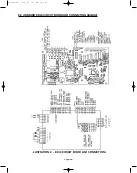
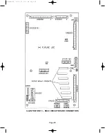
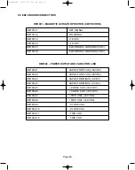
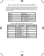
The ED2.0 board provides access through KM1003 for discharging the Storage Unit
capacitors. Make sure the ED2.0 Control Board Power is removed before attempting to
discharge the capacitors.
PROCEDURE:
A 10 kOhm capacitor discharge resistor is mounted on the circuit board. Discharging is done
by jumpering KM1003 pins 5 and 6. The time constant is 33 minutes. An external resistor can
be used for quicker discharging, but the discharge current should be restricted to 10 A
maximum. This means that no lower than 10 Ohms external resistance should be used to
perform capacitor discharging. In this case an external 10 Ohm, 25 watt resistor can be
connected to KM1003 Pins 5 and 6. Approximately 30 seconds is needed to discharge the
capacitors using the 10 Ohm external resistor.
6.2 CAPACITOR LIFE
The 0.1 Farad Electrolytic capacitors are designed to be operated in the temperature range of
-40°F to 185°F. The End of Life corresponds to the point at which the capacitance decreases
by 20% or more. It is recommended that replacement of capacitors be performed every 15
years for tropical climates and 20 years for an average yearly temperature (in the outdoor
breaker enclosure) of less than 122°F.
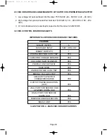
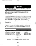
ILLUSTRATION 5 – CB OPERATIONS VS AVAILABLE CAPACITOR CHARGE
Page 37
CIRCUIT BREAKER POSITION
CAPACITOR CHARGE
CLOSE
OPEN
Energy sufficient for O-CO operations
Open allowed
Close allowed
Energy sufficient for CO operations
Open allowed
Close allowed
Energy sufficient for O operations
Open allowed
Blocked in open position
Energy insufficient for any operation
Blocked in closed
Blocked in open position
position or CB
opened (depending
on dip switch setting
- I1004)
WARNING
Make sure ED2.0 Control Power is removed before attempting to discharge the
capacitors. See paragraph below.
38-929M-15A 10/15/02 1:11 PM Page 41
Summary of Contents for R-MAG Series
Page 2: ...38 929M 15A 10 15 02 1 11 PM Page 2 ...
Page 4: ...38 929M 15A 10 15 02 1 11 PM Page 4 ...
Page 15: ...Page 11 Figure 3 Interrupter Assembly 1200 A 38 929M 15A 10 15 02 1 11 PM Page 15 ...
Page 16: ...Page 12 Figure 4 Interrupter Assembly 2000 A 38 929M 15A 10 15 02 1 11 PM Page 16 ...
Page 17: ...Page 13 Figure 5 Interrupter Assembly 3000 A 38 929M 15A 10 15 02 1 11 PM Page 17 ...
Page 20: ...Figure 8 Trip Handle Page 16 38 929M 15A 10 15 02 1 11 PM Page 20 ...
Page 21: ...Figure 9 High Voltage Cabinet Layout Page 17 38 929M 15A 10 15 02 1 11 PM Page 21 ...
Page 22: ...Figure 10 Typical Schematic Diagram Page 18 38 929M 15A 10 15 02 1 11 PM Page 22 ...
Page 23: ...Figure 11 Typical Connecting Diagram Page 19 38 929M 15A 10 15 02 1 11 PM Page 23 ...
Page 24: ...Figure 12 Typical Outline 1200 A Page 20 38 929M 15A 10 15 02 1 11 PM Page 24 ...
Page 25: ...Figure 13 Typical Outline 2000 3000 A Page 21 38 929M 15A 10 15 02 1 11 PM Page 25 ...
Page 30: ...Page 26 38 929M 15A 10 15 02 1 11 PM Page 30 ...
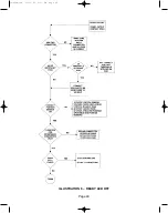
Page 44: ...Page 40 ILLUSTRATION 8 READY LED OFF 38 929M 15A 10 15 02 1 11 PM Page 44 ...
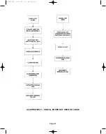
Page 45: ...Page 41 ILLUSTRATION 9 CB WILL EITHER NOT OPEN OR CLOSE 38 929M 15A 10 15 02 1 11 PM Page 45 ...

