2.0 INTRODUCTION
These instructions do not attempt to provide the user of this equipment with every possible
difficulty which may occur in the application, operation and maintenance of the product. Also,
as improvement in parts and assemblies are made, some parts may differ in appearance as
depicted in the illustrations; however, functionality will be equivalent.
The Type R-MAG Vacuum breaker is a high-voltage, three-phase device incorporating three
vacuum interrupters gang operated by a magnetic actuator. Together with the optional relaying
and current transformers, the breaker will sense an overload and automatically open.
Satisfactory performance of the breaker is contingent upon the correct installation, adequate
maintenance and service of the product. Careful study of these instructions will permit the
user to obtain maximum benefit from this device.
3.0 RECEIVING, HANDLING AND STORAGE
Each breaker is assembled and tested at the factory prior to being prepared for shipment.
This equipment was packed and shipped in factory new condition. If damage is noted, call the
carrier at once for inspection, and request an inspection report. File a formal claim with the
carrier, supported with paid freight bill, inspection report, and invoice. The local ABB Sales
Office must be notified. Normally this must be done within 10 days of receipt or receiver
assumes all responsibility for damage.
3.1 Receiving Inspection
Upon receipt, it is important to inspect promptly to be certain that the correct material has
been received. In case of shortage, immediately notify the local ABB Sales Office.
Check all parts against the shipping list as they are unpacked. Instructions and literature packed
with the breaker should be kept with the unit. The cabinet provides a convenient place to keep
this instruction book, a copy of the schematic diagram, and the card carrying the service record
of the unit. Additional copies may be obtained upon request from the local ABB Sales Office.
If the breaker is not to be placed in service immediately, it is essential that proper care be
exercised in the handling and storage to ensure good operating conditions in the future.
(See 3.3 - Storage)
3.2 Handling
The R-MAG solid dielectric breaker comes with two brackets that attach to the sides of the
cabinet and provide provisions for lifting the breaker. A two-point lift is recommended using
the loops in these brackets. (See Figure 2)
Page 2
38-929M-15A 10/15/02 1:11 PM Page 6
Summary of Contents for R-MAG Series
Page 2: ...38 929M 15A 10 15 02 1 11 PM Page 2 ...
Page 4: ...38 929M 15A 10 15 02 1 11 PM Page 4 ...
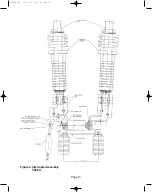
Page 15: ...Page 11 Figure 3 Interrupter Assembly 1200 A 38 929M 15A 10 15 02 1 11 PM Page 15 ...
Page 16: ...Page 12 Figure 4 Interrupter Assembly 2000 A 38 929M 15A 10 15 02 1 11 PM Page 16 ...
Page 17: ...Page 13 Figure 5 Interrupter Assembly 3000 A 38 929M 15A 10 15 02 1 11 PM Page 17 ...
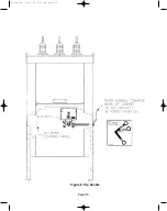
Page 20: ...Figure 8 Trip Handle Page 16 38 929M 15A 10 15 02 1 11 PM Page 20 ...
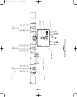
Page 21: ...Figure 9 High Voltage Cabinet Layout Page 17 38 929M 15A 10 15 02 1 11 PM Page 21 ...
Page 22: ...Figure 10 Typical Schematic Diagram Page 18 38 929M 15A 10 15 02 1 11 PM Page 22 ...
Page 23: ...Figure 11 Typical Connecting Diagram Page 19 38 929M 15A 10 15 02 1 11 PM Page 23 ...
Page 24: ...Figure 12 Typical Outline 1200 A Page 20 38 929M 15A 10 15 02 1 11 PM Page 24 ...
Page 25: ...Figure 13 Typical Outline 2000 3000 A Page 21 38 929M 15A 10 15 02 1 11 PM Page 25 ...
Page 30: ...Page 26 38 929M 15A 10 15 02 1 11 PM Page 30 ...
Page 44: ...Page 40 ILLUSTRATION 8 READY LED OFF 38 929M 15A 10 15 02 1 11 PM Page 44 ...
Page 45: ...Page 41 ILLUSTRATION 9 CB WILL EITHER NOT OPEN OR CLOSE 38 929M 15A 10 15 02 1 11 PM Page 45 ...


