RADIATION WARNING:
High voltage applied across an open gap in a vacuum can produce X-
radiation. No radiation is emitted when the breaker is closed, since no gap exists. Also, when the
breaker is open to the specified contact spacing in service or tested within the voltages specified,
X-radiation at one meter is below the level of concern. A danger could exist at voltages above or
contact spacing below that specified on the nameplate.
1. With the breaker in the open position, jumper both sets of three top terminals. Ground one
set of terminals and the housing. Connect the high voltage to the other set of terminals.
2. Stand clear more than one meter before energizing the high voltage source.
3. Do not exceed 37.5 kV.
4. If internal flashover occurs, isolate the phases and test each one independently to identify
the defective interrupter. Any defective pole assembly must be replaced prior to the breaker
being in service.
9.2 Replacement of Vacuum Interrupter Assemblies
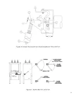
(See Figures 3-8)
The following procedure is made with the R-MAG breaker in the open position, control power off
and locked out, and stored energy capacitors discharged.
Removing the existing interrupter assemblies:
1. Using pliers, expand the "X" type retaining rings (G) at the top of the pullrod (A) and discon-
nect the pullrod from the triangle bellcranks. (Figure 8)
2. Loosen hardware at the point where the bottom of the bushing studs attach to each end of
the top of the interrupter bus assemblies (M) and remove hardware. (Figures 3-7)
3. Loosen the mounting hardware that fastens the interrupter assembly to the top of the
insulators (N). (Figures 3-7)
4. With the loosened hardware removed, lift the interrupter assembly from the breaker. Repeat
for all three phases.
Installing the new interrupter assemblies:
5. Replace with new interrupter assemblies (contact ABB for instructions on installation) on all
three phases using the new hardware provided. (Figures 3-7)
6. After all interrupter assemblies are in place, reinstall the triangle bellcranks to the top of the
pullrod (G) using the new "X" type retaining washers provided and compress the "X" rings
with pliers. (Figures 3-7)
10
9.1 High Pot Test
CAUTION
If power is removed from unit, and the Dip Switch I1004-1 is placed in the “on”
position, the breaker will automatically trip in approximately 3 minutes. Make
sure personnel and tools are clear from breaker.
!
Summary of Contents for R-MAG
Page 12: ...Figure 3 Interrupter Assembly 15 5 kV 1250 A 12 ...
Page 13: ...Figure 4 Interrupter Assembly 15 5 kV 2000 A 13 ...
Page 14: ...Figure 5 Interrupter Assembly 15 5 kV 3000 A 3700 FA 14 ...
Page 15: ...Figure 6 Interrupter Assembly 27 kV 1250 A 15 ...
Page 16: ...Figure 7 Interrupter Assembly 27 kV 2000 A 16 ...
Page 19: ...19 Figure 11 High Voltage Cabinet Layout 15 5 and 27 kV ...
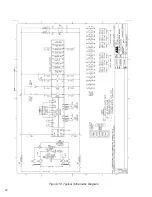
Page 20: ...20 Figure 12 Typical Schematic Diagram ...
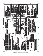
Page 21: ...Figure 13 Standard ED2 0 Circuit Board 21 ...
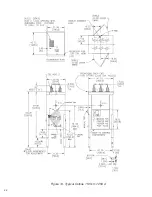
Page 22: ...22 Figure 14 Typical Outline 15 5 kV 1250 A ...
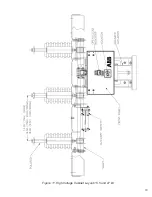
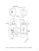
Page 23: ...23 Figure 15 Typical Outline 15 5 kV 2000 3000 3700 A and 27 kV 1250 2000 A ...
Page 40: ...40 9 0 TROUBLESHOOTING FLOWCHARTS ILLUSTRATION 5 READY LED CONTINUALLY FLASHING ...
Page 41: ...41 ILLUSTRATION 6 READY LED OFF ...
Page 42: ...42 ILLUSTRATION 7 CB WILL EITHER NOT OPEN OR CLOSE ...
Page 50: ...NOTES 50 ...
Page 51: ...NOTES 51 ...


