Table Of Contents
Description
Page
Safety Notices . . . . . . . . . . . . . . . . . . . . . . . . . . . . . . . . . . . . . . . . . . . . . . . . . . . . . . . . . . . . . . .3
Introduction . . . . . . . . . . . . . . . . . . . . . . . . . . . . . . . . . . . . . . . . . . . . . . . . . . . . . . . . . . . . . . . . .4
Receiving, Handling and Storage . . . . . . . . . . . . . . . . . . . . . . . . . . . . . . . . . . . . . . . . . . . . . . . .4
General Description . . . . . . . . . . . . . . . . . . . . . . . . . . . . . . . . . . . . . . . . . . . . . . . . . . . . . . . . . .5
Standard Production Tests . . . . . . . . . . . . . . . . . . . . . . . . . . . . . . . . . . . . . . . . . . . . . . . . . . . . .6
Operation . . . . . . . . . . . . . . . . . . . . . . . . . . . . . . . . . . . . . . . . . . . . . . . . . . . . . . . . . . . . . . . . . . .6
Operational Check Prior to Installation . . . . . . . . . . . . . . . . . . . . . . . . . . . . . . . . . . . . . . . . . . . .7
Installation . . . . . . . . . . . . . . . . . . . . . . . . . . . . . . . . . . . . . . . . . . . . . . . . . . . . . . . . . . . . . . . . . .8
Inspection, Maintenance and Adjustment . . . . . . . . . . . . . . . . . . . . . . . . . . . . . . . . . . . . . . . . . .9
R-MAG 15.5 kV Electrical Specifications . . . . . . . . . . . . . . . . . . . . . . . . . . . . . . . . . . . . . . . . .24
R-MAG 27 kV Electrical Specifications . . . . . . . . . . . . . . . . . . . . . . . . . . . . . . . . . . . . . . . . . . .25
Appendix A: Installation/Maintenance Instructions ED2.0 Magnetic Actuator Control Board . .28
List Of Illustrations
Description
Page
Figure 1. Hazardous Voltage Nameplate . . . . . . . . . . . . . . . . . . . . . . . . . . . . . . . . . . . . . . . . . .3
Figure 2. Lifting Detail . . . . . . . . . . . . . . . . . . . . . . . . . . . . . . . . . . . . . . . . . . . . . . . . . . . . . . . . .5
Figure 3. Interrupter Assembly, 15.5 kV, 1200 A . . . . . . . . . . . . . . . . . . . . . . . . . . . . . . . . . . . .12
Figure 4. Interrupter Assembly, 15.5 kV, 2000 A . . . . . . . . . . . . . . . . . . . . . . . . . . . . . . . . . . . .13
Figure 5. Interrupter Assembly, 15.5 kV, 3000/3700 A . . . . . . . . . . . . . . . . . . . . . . . . . . . . . . .14
Figure 6. Interrupter Assembly, 27 kV, 1250 A . . . . . . . . . . . . . . . . . . . . . . . . . . . . . . . . . . . . .15
Figure 7. Interrupter Assembly, 27 kV, 2000 A . . . . . . . . . . . . . . . . . . . . . . . . . . . . . . . . . . . . .16
Figure 8. Contact Travel and Over-Travel Adjustment . . . . . . . . . . . . . . . . . . . . . . . . . . . . . . .17
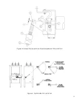
Figure 9. Trip Handle, 15.5 and 27 kV . . . . . . . . . . . . . . . . . . . . . . . . . . . . . . . . . . . . . . . . . . .17
Figure 10. Contact Erosion Graphs, 15.5 and 27 kV . . . . . . . . . . . . . . . . . . . . . . . . . . . . . . . .18
Figure 11. High Voltage Cabinet Layout, 15.5 and 27 kV . . . . . . . . . . . . . . . . . . . . . . . . . . . . .19
Figure 12. Typical Schematic Diagram . . . . . . . . . . . . . . . . . . . . . . . . . . . . . . . . . . . . . . . . . . .20
Figure 13. Standard ED2.0 Circuit Board . . . . . . . . . . . . . . . . . . . . . . . . . . . . . . . . . . . . . . . . .21
Figure 14. Typical Outline 15.5 kV, 1200 A . . . . . . . . . . . . . . . . . . . . . . . . . . . . . . . . . . . . . . . .22
Figure 15. Typical Outline 15.5 kV, 2000/3000/3700 A and 27 kV, 1200/2000 A . . . . . . . . . . .23
Figure 16. Breaker Nameplate . . . . . . . . . . . . . . . . . . . . . . . . . . . . . . . . . . . . . . . . . . . . . . . . .27
2
Summary of Contents for R-MAG
Page 12: ...Figure 3 Interrupter Assembly 15 5 kV 1250 A 12 ...
Page 13: ...Figure 4 Interrupter Assembly 15 5 kV 2000 A 13 ...
Page 14: ...Figure 5 Interrupter Assembly 15 5 kV 3000 A 3700 FA 14 ...
Page 15: ...Figure 6 Interrupter Assembly 27 kV 1250 A 15 ...
Page 16: ...Figure 7 Interrupter Assembly 27 kV 2000 A 16 ...
Page 19: ...19 Figure 11 High Voltage Cabinet Layout 15 5 and 27 kV ...
Page 20: ...20 Figure 12 Typical Schematic Diagram ...
Page 21: ...Figure 13 Standard ED2 0 Circuit Board 21 ...
Page 22: ...22 Figure 14 Typical Outline 15 5 kV 1250 A ...
Page 23: ...23 Figure 15 Typical Outline 15 5 kV 2000 3000 3700 A and 27 kV 1250 2000 A ...
Page 40: ...40 9 0 TROUBLESHOOTING FLOWCHARTS ILLUSTRATION 5 READY LED CONTINUALLY FLASHING ...
Page 41: ...41 ILLUSTRATION 6 READY LED OFF ...
Page 42: ...42 ILLUSTRATION 7 CB WILL EITHER NOT OPEN OR CLOSE ...
Page 50: ...NOTES 50 ...
Page 51: ...NOTES 51 ...


