29
Table Of Contents
Description
Page
1.0 OVERVIEW
. . . . . . . . . . . . . . . . . . . . . . . . . . . . . . . . . . . . . . . . . . . . . . . . . . . . . . . . . . . . .30
2.0 ED2.0 BOARDS AVAILABLE/MAGNETIC COIL ENERGIZING CAPACITOR
. . . . . . . . .31
3.0 BINARY INPUTS
. . . . . . . . . . . . . . . . . . . . . . . . . . . . . . . . . . . . . . . . . . . . . . . . . . . . . . . .31
3.1 Remote Close (KM1005 Pins 1 & 2) . . . . . . . . . . . . . . . . . . . . . . . . . . . . . . . . . . . . . . . . . .31
3.2 Remote Open (KM1005 Pins 3 & 4) . . . . . . . . . . . . . . . . . . . . . . . . . . . . . . . . . . . . . . . . . .31
3.3 Auxiliary Open / Safe Open (KM1005 Pins 5 & 6) . . . . . . . . . . . . . . . . . . . . . . . . . . . . . . .31
3.4 Protection Trip / Second Trip (KM1005 Pins 7 & 8) . . . . . . . . . . . . . . . . . . . . . . . . . . . . . .32
3.5 Circuit Breaker Locked Open (KM1005 Pins 11 & 12) . . . . . . . . . . . . . . . . . . . . . . . . . . . .32
3.6 Under Voltage Trip (KM1005 Pins 13 and 14) . . . . . . . . . . . . . . . . . . . . . . . . . . . . . . . . . . .32
4.0 BINARY OUTPUTS
. . . . . . . . . . . . . . . . . . . . . . . . . . . . . . . . . . . . . . . . . . . . . . . . . . . . . . .33
4.1 Circuit Breaker Opened (KM1004 Pins 1 & 2) . . . . . . . . . . . . . . . . . . . . . . . . . . . . . . . . . .33
4.2 Circuit Breaker Closed (KM1004 Pins 3 & 4) . . . . . . . . . . . . . . . . . . . . . . . . . . . . . . . . . . .33
4.3 Circuit Breaker Auxiliary Open (KM1004 Pins 5 & 6) . . . . . . . . . . . . . . . . . . . . . . . . . . . . .33
4.4 Circuit Breaker Auxiliary Closed (KM1004 Pins 7 & 8) . . . . . . . . . . . . . . . . . . . . . . . . . . . .33
4.5 Unit Ready (KM1004 Pins 9 & 10) . . . . . . . . . . . . . . . . . . . . . . . . . . . . . . . . . . . . . . . . . . .33
4.6 Unit Not Ready (KM1004 Pins 11 & 12) . . . . . . . . . . . . . . . . . . . . . . . . . . . . . . . . . . . . . . .33
4.7 Circuit Breaker Remote Open (KM1004 Pins 13 & 14) . . . . . . . . . . . . . . . . . . . . . . . . . . .33
5.0 FEATURES
. . . . . . . . . . . . . . . . . . . . . . . . . . . . . . . . . . . . . . . . . . . . . . . . . . . . . . . . . . . . .35
5.1 Temperature Protection . . . . . . . . . . . . . . . . . . . . . . . . . . . . . . . . . . . . . . . . . . . . . . . . . . .35
5.2 Actuator Close and Trip Coil Continuity Monitor . . . . . . . . . . . . . . . . . . . . . . . . . . . . . . . . .35
5.3 Wrong Position Auto Trip . . . . . . . . . . . . . . . . . . . . . . . . . . . . . . . . . . . . . . . . . . . . . . . . . . .35
5.4 Energy Failure Auto Trip . . . . . . . . . . . . . . . . . . . . . . . . . . . . . . . . . . . . . . . . . . . . . . . . . . .35
5.5 Reduced Power Consumption . . . . . . . . . . . . . . . . . . . . . . . . . . . . . . . . . . . . . . . . . . . . . . .35
5.6 RS-232 Port / JTAG Communication Port . . . . . . . . . . . . . . . . . . . . . . . . . . . . . . . . . . . . . .35
6.0 POWER CONSIDERATIONS
. . . . . . . . . . . . . . . . . . . . . . . . . . . . . . . . . . . . . . . . . . . . . . .36
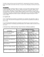
6.1 Discharging Storage Unit Capacitors . . . . . . . . . . . . . . . . . . . . . . . . . . . . . . . . . . . . . . . . . .36
6.2 Capacitor Life . . . . . . . . . . . . . . . . . . . . . . . . . . . . . . . . . . . . . . . . . . . . . . . . . . . . . . . . . . . .37
6.3 Breaker Ready / Not Ready Binary Output Contacts and Ready Light Status . . . . . . . . . .37
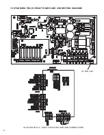
7.0 STANDARD ED2.0 CIRCUIT BOARD AND CONNECTING DIAGRAM
. . . . . . . . . . . . . .38
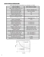
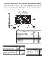
8.0 DEFAULT JUMPER AND DIP SWITCH SETTINGS
. . . . . . . . . . . . . . . . . . . . . . . . . . . . .39
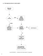
9.0 TROUBLESHOOTING FLOWCHARTS
. . . . . . . . . . . . . . . . . . . . . . . . . . . . . . . . . . . . . . .40
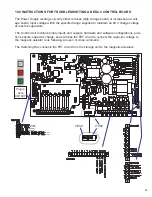
10.0 INSTRUCTIONS FOR TROUBLESHOOTING AN ED2.0 CONTROL BOARD
. . . . . . . .43
11.0 INSTRUCTIONS FOR CHANGING OUT AN ED2.0 BOARD
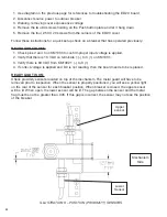
. . . . . . . . . . . . . . . . . . . . .48
11.0 NOTES
. . . . . . . . . . . . . . . . . . . . . . . . . . . . . . . . . . . . . . . . . . . . . . . . . . . . . . . . . . . . . . . .50
Summary of Contents for R-MAG
Page 12: ...Figure 3 Interrupter Assembly 15 5 kV 1250 A 12 ...
Page 13: ...Figure 4 Interrupter Assembly 15 5 kV 2000 A 13 ...
Page 14: ...Figure 5 Interrupter Assembly 15 5 kV 3000 A 3700 FA 14 ...
Page 15: ...Figure 6 Interrupter Assembly 27 kV 1250 A 15 ...
Page 16: ...Figure 7 Interrupter Assembly 27 kV 2000 A 16 ...
Page 19: ...19 Figure 11 High Voltage Cabinet Layout 15 5 and 27 kV ...
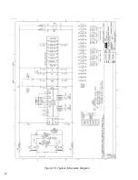
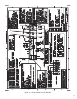
Page 20: ...20 Figure 12 Typical Schematic Diagram ...
Page 21: ...Figure 13 Standard ED2 0 Circuit Board 21 ...
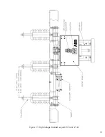
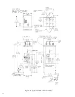
Page 22: ...22 Figure 14 Typical Outline 15 5 kV 1250 A ...
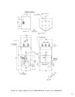
Page 23: ...23 Figure 15 Typical Outline 15 5 kV 2000 3000 3700 A and 27 kV 1250 2000 A ...
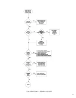
Page 40: ...40 9 0 TROUBLESHOOTING FLOWCHARTS ILLUSTRATION 5 READY LED CONTINUALLY FLASHING ...
Page 41: ...41 ILLUSTRATION 6 READY LED OFF ...
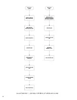
Page 42: ...42 ILLUSTRATION 7 CB WILL EITHER NOT OPEN OR CLOSE ...
Page 50: ...NOTES 50 ...
Page 51: ...NOTES 51 ...


