3.4 Protection Trip / Second Trip (KM1005, CH 4, Pins 7 and 8)
This input can be configured as either a Protection Trip or Second Trip function. It is programmed
via Jumper JP1001 Pins 1 and 2 or as a normal input by jumpering JP1001 pins 2 and 3.
The Protection Trip input is designed to work at a lower threshold of 7 VDC. This input is provid-
ed to use with special protection relay requirements. It can also be used as a normal trip input.
The Second Trip is often referred to as “Shunt Trip.” It functions the same as the Remote Input
with the exception of the input impedance which is 300 kOhms.
3.5 Circuit Breaker Locked Open (KM1005, CH 6, Pins 11 and 12)
The Circuit Breaker Locked Open feature functions like the familiar 69 switch. The circuit is deen-
ergized when the external trip handle is moved from its normal position (i.e., in the trip position).
In this position the breaker cannot be either locally or remotely closed.
When the circuit breaker is tripped, by operating the manual trip handle, the breaker will go into
the Open Lock mode. This prevents any future closings until the Trip Handle is returned to the
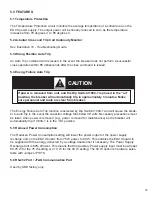
Normal Position. The Manual Trip Handle must be left in the down position for the switch to
remain open (i.e., locked open). It is important that the handle be moved all the way to the bot-
tom of the trip position to enable this function.
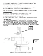
There is a padlock provision for locking the manual lever in the Locked Open position.
See figure 9.
3.6 Under Voltage Trip (KM1005, CH 7, Pins 13 and 14)
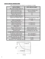
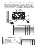
The Under Voltage Trip input will perform an auto trip in the event the voltage source being moni-
tored, by this input, falls between 35% to 70% of nominal. It is enabled through DIP Switch
I1004/2-3-4. The response of this input also has a programmable time delay from 500 millisec-
onds to 5 seconds. The delay is set by the various combinations of DIP Switch I1004/2-3-4. The
Under Voltage Threshold is set by I1001. See Table below.
32
DIP SWITCH I1001 POSITION
THRESHOLD
1
100 – 127 VAC/DC
2
48 – 60 VDC
3
24 – 30 VDC
NONE
220 – 240 VAC/DC
Summary of Contents for R-MAG
Page 12: ...Figure 3 Interrupter Assembly 15 5 kV 1250 A 12 ...
Page 13: ...Figure 4 Interrupter Assembly 15 5 kV 2000 A 13 ...
Page 14: ...Figure 5 Interrupter Assembly 15 5 kV 3000 A 3700 FA 14 ...
Page 15: ...Figure 6 Interrupter Assembly 27 kV 1250 A 15 ...
Page 16: ...Figure 7 Interrupter Assembly 27 kV 2000 A 16 ...
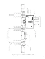
Page 19: ...19 Figure 11 High Voltage Cabinet Layout 15 5 and 27 kV ...
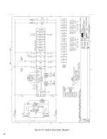
Page 20: ...20 Figure 12 Typical Schematic Diagram ...
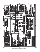
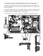
Page 21: ...Figure 13 Standard ED2 0 Circuit Board 21 ...
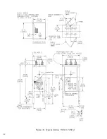
Page 22: ...22 Figure 14 Typical Outline 15 5 kV 1250 A ...
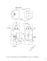
Page 23: ...23 Figure 15 Typical Outline 15 5 kV 2000 3000 3700 A and 27 kV 1250 2000 A ...
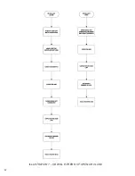
Page 40: ...40 9 0 TROUBLESHOOTING FLOWCHARTS ILLUSTRATION 5 READY LED CONTINUALLY FLASHING ...
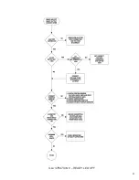
Page 41: ...41 ILLUSTRATION 6 READY LED OFF ...
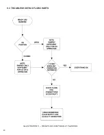
Page 42: ...42 ILLUSTRATION 7 CB WILL EITHER NOT OPEN OR CLOSE ...
Page 50: ...NOTES 50 ...
Page 51: ...NOTES 51 ...

