35
5.0 FEATURES
5.1 Temperature Protection
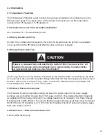
The Temperature Protection circuit monitors the average temperature of a critical area on the
ED2.0 power supply. The output power will be linearly reduced to zero as the temperature
increases from 78 degrees C to 95 degrees C.
5.2 Actuator Close and Trip Coil Continuity Monitor
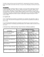
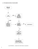
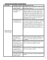
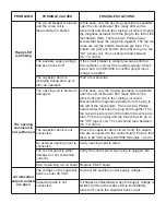
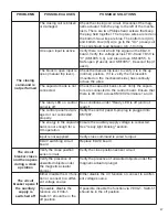
See Illustration 10 - Troubleshooting Guide.
5.3 Wrong Position Auto Trip
An Auto Trip command will be issued in the event the breaker does not perform a successful
close operation within 95 milliseconds after the close command is issued.
5.4 Energy Failure Auto Trip
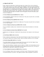
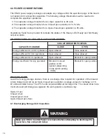
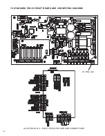
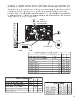
The Energy Failure Auto Trip function is selected by Dip Switch I1004-1 and will cause the break-
er to auto trip in the event the capacitor voltage falls below 49 volts. Necessary precautions must
be taken when power is removed (e.g., power removed for maintenance) as the breaker will
automatically trip if I1004-1 is in the “On” position.
5.5 Reduced Power Consumption
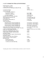
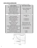
The Reduced Power Consumption setting will lower the power output of the power supply
recharge unit, on the ED2.0 board, from 75 W power to 33 W. This enables the ED2.0 board to
be supplied with the energy delivered by a voltage transformer if necessary. The Power Supply
Recharge Unit is 80% efficient. This means that the Auxiliary Power supply input must be at least
93.75 W for the 75 W setting or 41.3 W for the 33 W setting. The 33 W option is hardware selec-
table with Jumper JP1019.
5.6 RS-232 Port / JTAG Communication Port
Used by ABB factory only.
CAUTION
If power is removed from unit, and the Dip Switch I1004-1 is placed in the “on”
position, the breaker will automatically trip in approximately 3 minutes. Make
sure personnel and tools are clear from breaker.
!
Summary of Contents for R-MAG
Page 12: ...Figure 3 Interrupter Assembly 15 5 kV 1250 A 12 ...
Page 13: ...Figure 4 Interrupter Assembly 15 5 kV 2000 A 13 ...
Page 14: ...Figure 5 Interrupter Assembly 15 5 kV 3000 A 3700 FA 14 ...
Page 15: ...Figure 6 Interrupter Assembly 27 kV 1250 A 15 ...
Page 16: ...Figure 7 Interrupter Assembly 27 kV 2000 A 16 ...
Page 19: ...19 Figure 11 High Voltage Cabinet Layout 15 5 and 27 kV ...
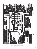
Page 20: ...20 Figure 12 Typical Schematic Diagram ...
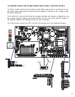
Page 21: ...Figure 13 Standard ED2 0 Circuit Board 21 ...
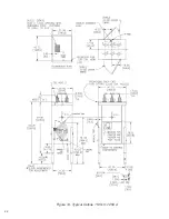
Page 22: ...22 Figure 14 Typical Outline 15 5 kV 1250 A ...
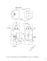
Page 23: ...23 Figure 15 Typical Outline 15 5 kV 2000 3000 3700 A and 27 kV 1250 2000 A ...
Page 40: ...40 9 0 TROUBLESHOOTING FLOWCHARTS ILLUSTRATION 5 READY LED CONTINUALLY FLASHING ...
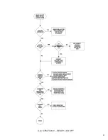
Page 41: ...41 ILLUSTRATION 6 READY LED OFF ...
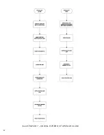
Page 42: ...42 ILLUSTRATION 7 CB WILL EITHER NOT OPEN OR CLOSE ...
Page 50: ...NOTES 50 ...
Page 51: ...NOTES 51 ...

