45
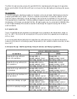
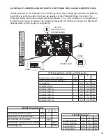
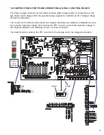
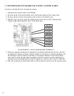
SPECIFIC LINE ITEM CHECK IS SHOWN BELOW:
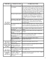
The auxiliary supply
voltage is absent.
Check pins 2 and 3 on KM1003 to confirm proper
input voltage is applied.
PROBLEMS
POSSIBLE CAUSES
POSSIBLE SOLUTIONS
Ready LED is off
(unit not ready)
The magnetic actuator
is damaged or not
connected.
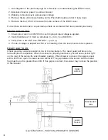
Check the magnetic actuator circuit. Unplug the
magnetic actuator from the plug to the left of the
mechanism (MA). There are two Phillips head
screws that keep the plug held together. The top
two wires are red the bottom two wires are blue.
The bottom red (43) and bottom blue (45) wire go
to the "On" (close) coil. The other two wires go to
the off (open) coil. Each of these coils should
read between 0.6 -1.0 ohms.
The position sensors
are damaged or not
connected correctly.
There are 3 wires connected to the proximity sen-
sors- Black is the signal wire, Brown is connected
to +18 volts and Blue is connected to ground.
When metal is placed in front of a sensor, it will
be picked up and you will see the yellow LED lit
on the back of the sensor. From the black wire to
the blue wire verify it reads +18V. When the
metal is removed the voltage should drop to near
0.
The Under Voltage
(UV) function is
enabled and input is
open.
Inspect dip switch I1004. Ensure switches 2, 3, 4
and 5 are in the off (down) position (disables UV),
or apply correct input voltage to pins 13 and 14
on KM1005.
The UV function is
enabled and the moni-
tored voltage is con-
nected to the UV input,
but the voltage is lower
than the threshold.
Set the correct UV threshold level via DIP switch
I1001 or disable UV by putting switches 2, 3, 4
and 5 in the off (down) position on I1004.
The auxiliary supply
voltage has been
turned off and the volt-
age on the capacitor is
under the O-CO levels.
Check pins 2 and 3 on KM1003 to confirm proper
source input voltage is applied.
The control panel is
damaged or not con-
nected correctly.
Verify the control panel 6-pin plug is plugged into
KM1007.
Summary of Contents for R-MAG
Page 12: ...Figure 3 Interrupter Assembly 15 5 kV 1250 A 12 ...
Page 13: ...Figure 4 Interrupter Assembly 15 5 kV 2000 A 13 ...
Page 14: ...Figure 5 Interrupter Assembly 15 5 kV 3000 A 3700 FA 14 ...
Page 15: ...Figure 6 Interrupter Assembly 27 kV 1250 A 15 ...
Page 16: ...Figure 7 Interrupter Assembly 27 kV 2000 A 16 ...
Page 19: ...19 Figure 11 High Voltage Cabinet Layout 15 5 and 27 kV ...
Page 20: ...20 Figure 12 Typical Schematic Diagram ...
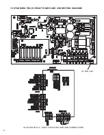
Page 21: ...Figure 13 Standard ED2 0 Circuit Board 21 ...
Page 22: ...22 Figure 14 Typical Outline 15 5 kV 1250 A ...
Page 23: ...23 Figure 15 Typical Outline 15 5 kV 2000 3000 3700 A and 27 kV 1250 2000 A ...
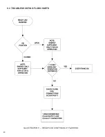
Page 40: ...40 9 0 TROUBLESHOOTING FLOWCHARTS ILLUSTRATION 5 READY LED CONTINUALLY FLASHING ...
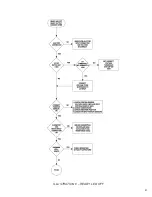
Page 41: ...41 ILLUSTRATION 6 READY LED OFF ...
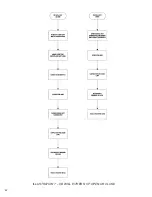
Page 42: ...42 ILLUSTRATION 7 CB WILL EITHER NOT OPEN OR CLOSE ...
Page 50: ...NOTES 50 ...
Page 51: ...NOTES 51 ...

