47
PROBLEMS
POSSIBLE CAUSES
POSSIBLE SOLUTIONS
The closing
command is
not performed
The closing coil is broken
or damaged.
Check the closing coil circuit. Disconnect the mag-
netic actuator from the plug to the left of the mecha-
nism. There are two Phillips head screws that keep
the plug held together. The top two wires are red and
the bottom two wires are blue. The bottom red (43)
and bottom blue (45) wire go to the "On" (close) coil.
The coil should read between 0.6 -1.0 ohms.
One open input is active.
Verify there is not a held trip signal on the ED2.0
board. Verify the voltage across TB1-8 and TB1-3 is
"0" (KM1005 3, 4), and also across KM1005 5, 6
Safe open (if used), and KM1005 7, 8 second trip (if
used).
The block in open input is
open (manual trip lever).
Check the manual trip lever to verify it is in the up
(normal) position. If it is, verify the microswitch
(mounted on the mechanism side) has continuity
across the wires.
The capacitor bank is not
connected.
Check the capacitor bank circuit. Verify the capaci-
tors are connected to the control board. Ensure that
there is 80 VDC across KM1002 terminals 1 and 3.
The ready LED on control
panel is off.
See conditions under "Ready LED is off (unit not
ready)".
The control panel is dam-
aged or not connected
properly.
Verify the control panel 6-pin plug is plugged into
KM1007.
The energy in the capacitor
bank is not enough for a
CO-operation.
Ensure the auxiliary supply voltage is connected.
See "ready light blinking" section.
input is not supplied.
Verify close command is wired to input.
ED2.0 switching circuit
board
Replace ED2.0 board
The circuit
breaker closes
and then opens
during a close
operation
Verify the close position
sensor circuit.
Verify the close position sensor circuit.
Verify the presence of
unwanted objects under
the magnetic actuator
plunger.
Verify the presence of unwanted objects under the
magnetic actuator plunger.
The circuit
breaker opens if
the auxiliary
supply is
switched off
Either disable the UV func-
tion or connect to a differ-
ent voltage source.
Either disable the UV function or connect to a differ-
ent voltage source.
If possible, disable the
function via I1004-1.
Switch 1 should be in the
off position.
If possible, disable the function via I1004-1. Switch 1
should be in the off position.
Summary of Contents for R-MAG
Page 12: ...Figure 3 Interrupter Assembly 15 5 kV 1250 A 12 ...
Page 13: ...Figure 4 Interrupter Assembly 15 5 kV 2000 A 13 ...
Page 14: ...Figure 5 Interrupter Assembly 15 5 kV 3000 A 3700 FA 14 ...
Page 15: ...Figure 6 Interrupter Assembly 27 kV 1250 A 15 ...
Page 16: ...Figure 7 Interrupter Assembly 27 kV 2000 A 16 ...
Page 19: ...19 Figure 11 High Voltage Cabinet Layout 15 5 and 27 kV ...
Page 20: ...20 Figure 12 Typical Schematic Diagram ...
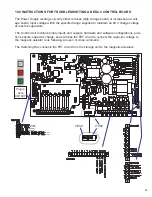
Page 21: ...Figure 13 Standard ED2 0 Circuit Board 21 ...
Page 22: ...22 Figure 14 Typical Outline 15 5 kV 1250 A ...
Page 23: ...23 Figure 15 Typical Outline 15 5 kV 2000 3000 3700 A and 27 kV 1250 2000 A ...
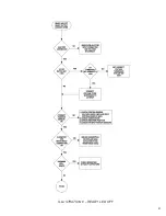
Page 40: ...40 9 0 TROUBLESHOOTING FLOWCHARTS ILLUSTRATION 5 READY LED CONTINUALLY FLASHING ...
Page 41: ...41 ILLUSTRATION 6 READY LED OFF ...
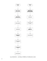
Page 42: ...42 ILLUSTRATION 7 CB WILL EITHER NOT OPEN OR CLOSE ...
Page 50: ...NOTES 50 ...
Page 51: ...NOTES 51 ...

