49
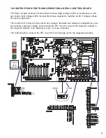
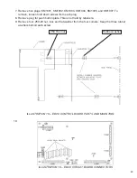
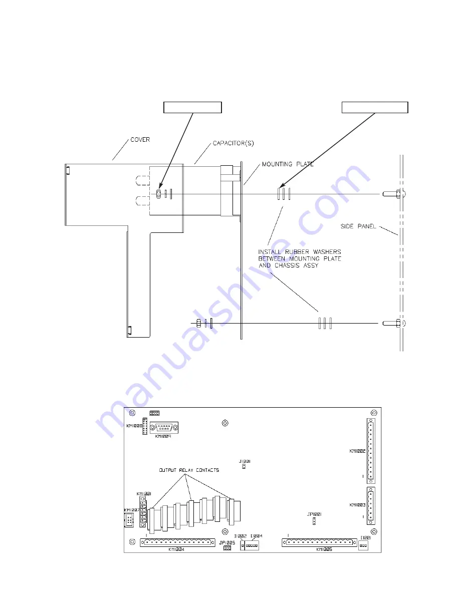
7. Remove five plugs: KM1001, KM1002, KM1003, KM1004, KM1005, and KM1007. To
remove, loosen hold down screws from each plug.
8. Remove plug for push button plate. This is not held by retainers.
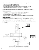
9. Remove four .250-20 nut, lock and flat washer from the four corners. Keep the three rubber
washers behind each screw.
10.
.250 Hex nut
Rubber washer
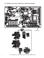
ILLUSTRATION 10 – ED2.0 CONTROL BOARD PARTS AND MOUNTING
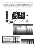
ILLUSTRATION 10 – ED2.0 CIRCUIT BOARD CONNECTORS
Summary of Contents for R-MAG
Page 12: ...Figure 3 Interrupter Assembly 15 5 kV 1250 A 12 ...
Page 13: ...Figure 4 Interrupter Assembly 15 5 kV 2000 A 13 ...
Page 14: ...Figure 5 Interrupter Assembly 15 5 kV 3000 A 3700 FA 14 ...
Page 15: ...Figure 6 Interrupter Assembly 27 kV 1250 A 15 ...
Page 16: ...Figure 7 Interrupter Assembly 27 kV 2000 A 16 ...
Page 19: ...19 Figure 11 High Voltage Cabinet Layout 15 5 and 27 kV ...
Page 20: ...20 Figure 12 Typical Schematic Diagram ...
Page 21: ...Figure 13 Standard ED2 0 Circuit Board 21 ...
Page 22: ...22 Figure 14 Typical Outline 15 5 kV 1250 A ...
Page 23: ...23 Figure 15 Typical Outline 15 5 kV 2000 3000 3700 A and 27 kV 1250 2000 A ...
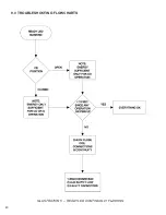
Page 40: ...40 9 0 TROUBLESHOOTING FLOWCHARTS ILLUSTRATION 5 READY LED CONTINUALLY FLASHING ...
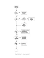
Page 41: ...41 ILLUSTRATION 6 READY LED OFF ...
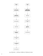
Page 42: ...42 ILLUSTRATION 7 CB WILL EITHER NOT OPEN OR CLOSE ...
Page 50: ...NOTES 50 ...
Page 51: ...NOTES 51 ...

