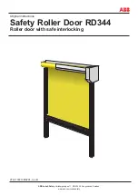
background image

ABB Jokab Safety

 Varlabergsvägen 11, SE-434 39 Kungsbacka, Sweden

www.abb.com/jokabsafety

2TLC172213M0201

rev. B

Original instructions

Safety Roller Door RD344

Roller door with safe interlocking

Summary of Contents for RD344

Page 1: ...ABB Jokab Safety Varlabergsvägen 11 SE 434 39 Kungsbacka Sweden www abb com jokabsafety 2TLC172213M0201 rev B Original instructions Safety Roller Door RD344 Roller door with safe interlocking ...

Page 2: ... will provide applicable third party certification documents identifying ratings and limitations of use that apply to the products This information by itself is not sufficient for a complete determination of the suitability of the products in combination with the end product machine system or other application or use The following are some examples of applications for which particular attention mu...

Page 3: ...Frame 14 Step 2 Back Plate 14 Step 3 Aligning 14 Step 4 Attachment 14 Step 5 Fit the drive unit 15 Step 6 Roller package 15 Step 7 Centering 16 5 Electrical installation 17 Cable requirements 17 Electrical conditions 17 Electrical installation step by step 17 Step 8 Drive unit 17 Step 9 Electrical cabinet 18 6 Adjustments testing and mounting of cover plates 19 Final installation step by step 19 S...

Page 4: ...2TLC172213M0201 rev B 4 www abb com jokabsafety 9 Maintenance 24 10 Technical data 25 11 EC Declaration of Conformity 26 12 Connection examples 27 ...

Page 5: ...umed that the reader of this document has knowledge of the following Basic knowledge of ABB Jokab Safety products Knowledge of machine safety Special notes Pay attention to the following special notes in the document Warning Danger of severe personal injury An instruction or procedure which if not carried out correctly may result in injury to the technician or other personnel Caution Danger of dam...

Page 6: ...g system are at hand when mounting the door in other types of guarding or fixture that it is of suitable strength and capable of rigidly supporting the door see section 2 2 that all components according to delivery note are at hand and undamaged see parts list section 4 1 NB When installing the door it is of vital importance that the frame columns are erected absolutely vertically and the top roll...

Page 7: ...e and the operator can pass the door and go into the machine the door must be prevented from being closed and the machine being started while the operator is inside the machine area One way of doing this is to install a horizontal light curtain s to protect the area s where the operator can stand in the machine Another way of securing that nobody is inside the risk area when the door is to be oper...

Page 8: ... in balance without risk of tipping or dropping Use lifting equipment that is approved and suitable for the size and weight of the top roll Fasten the frames when dismantling When the frames have to be dismantled the upper parts must be secured with appropriate lifting equipment Fasten the drive unit when mounting dismantling When the drive unit is to be mounted dismantled it must be secured in ap...

Page 9: ...e machine is ready to be restarted When the door starts to open a stop signal is sent to the machine As the door has Eden sensors on both sides this prevents the door being lifted or pushed to one side without a stop signal being given to the machine To protect personnel from being injured by the door it is equipped with a contact strip on the bottom beam profile If the door hits a person the cont...

Page 10: ...d view 04 02 05 06 15 20 19 24 31 29 23 34 35 40 38 37 25 33 09 10 11 22 03 18 26 27 28 32 30 36 13 12 05 01 07 08 17 21 04 30 42 41 44 43 39 34 42 25 11 14 49 48 61 62 60 45 93 47 72 56 51 46 59 63 68 69 16 71 67 74 70 74 57 57 57 OPTION 73 54 53 52 55 38 46 50 64 66 65 85 77 79 78 84 80 81 75 88 87 86 89 90 82 83 76 91 92 ...

Page 11: ...ate 35 1 Fork moulding Left 36 1 Lower wall mounting Right 37 1 Cable chain 38 4 Decorative moulding frame JSM T3 39 1 Fork mounting Right Pos No Title Note 40 1 Lower wall mounting Left 41 2 Eden safety switch ADAM part 42 2 End position damper 43 1 End piece 2 m cable 44 1 End piece 2 m cable 45 2 ULG joint clamp 46 2 Sealing strip 17 47 1 Cable chain flex 48 1 Motor cable 49 1 Limit position ca...

Page 12: ...Pos No Title Note 80 2 Screw KT6 M6x12 81 2 Nut 82 6 Nut 83 2 Screw MLC6S M4x12 84 1 Manufacturing sign 85 1 Back plate motor cover Option 86 1 Nut 87 1 Screw MF6S M8x16 88 1 Velcro fastener 89 1 Screw KT6 M6x12 90 1 Nut 91 1 Screw KT6 M6x12 92 1 Nut ...

Page 13: ...abb com jokabsafety 13 2TLC172213M0201 rev B Fixing points 120 263 250 148 125 DW DH 450 80 252 DH A B 9 C 25 175 35 13 DETAIL A SCALE 1 2 DW 75 36 11 DETAIL B SCALE 1 2 60 1 1 36 DETAIL C SCALE 1 2 DW 100 ...

Page 14: ...lower wall attachments 36 40 See Figure 4 4 Step 3 Aligning Align the door using a spirit level or an aligning instrument and check that the top seal is horizontal and that the frames are vertical Step 2 Back Plate Mount the back plate 17 against the wall mountings upper edge The back plate determines the distance between the frames See Figure 4 3 Step 1 Frame Remove the cover profiles 19 and 22 f...

Page 15: ...non motor side See Figure 4 7 The screws for the bearing shall not be tightened Unscrew the two lower attachment screws on the bearing plate but leave the upper screw slightly loose so that it fits against the upper wall mounting See Figure 4 7 Lift the roller into position with the bearing side first Lower the roller so that the screw in the bearing plate fits into the wall mounting s long hole p...

Page 16: ...n the bearing plate and roller Install the bearing s excenter locking ring on the non motor side and turn clockwise Lock the locking ring by knocking it with hard blows for turn Use a drift that is inserted in a pre drilled hole Tighten the locking screw See Figure 4 10a d Tighten all the screws in the bearing same distance locking ring with locking screw Figure 4 9 Figure 4 10a Figure 4 10b 1 2 3...

Page 17: ...ording to IP54 Always use screw caps that preserve the IP class If the door is mounted in such a position that the drive unit could be affected by rain or wash down then the motor should be fitted with an additional cover Control voltage is 24 VDC Electrical installation step by step Step 8 Drive unit Connecting the motor Check that the motor is marked as follows 360 415 208 240 Volt 3 phase syste...

Page 18: ...tton signal for controlling door movement downwards 7 8 X3 Connection of external button signal for stopping the door 20 X3 Reset button 21 X3 Reset button 22 X3 Lamp in reset button 23 27 X3 Eden 1 Safety switch for supervision of closed position of the door 28 32 X3 Eden 2 Safety switch for supervision of closed position of the door 33 36 X3 Connection of contact strip 37 44 X3 Option Focus II R...

Page 19: ...th an Allen key Operate the door to a half open position Close the door again Fine adjust the CLOSE stop position by turning the adjustment screw 4 The CLOSE SAFETY cam switch follows the adjustments made on the CLOSE cam switch Fine adjustments can be made on CLOSE SAFETY by turning the adjustment screw 4 3 2 1 4 1 2 3 4 Cam Switch Lock screw Adjustments Figure 6 1 Cam switch Step 11 Adjustment o...

Page 20: ... S23 button on the control panel to close the door Adjust both adjustment plates 34 until the door s guide rails 25 rest in the bottom of both the fork brackets 30 The locking head 32 is mounted on the guide fitting s right or left sides See Figure 6 2 Adjust the Eden ADAM sensor 41 so that it is positioned opposite the Eden EVA sensor at a distance of no more than 8 mm See Figure 6 3 Check that t...

Page 21: ...H 450 DW 400 DW 160 A A D D H VKR 80x40x3 VKR 40x40x2 VKR 40x40x2 VKR 40x40x2 Pls 80x8x300 VKR 40x40x2 Pls 40x6 VKR 40x40x2 Drawing showing no pre drilled hole for door frame E SECTION A A SCALE 1 10 300 80 F SECTION D D SCALE 1 10 100 200 12 20 12 DETAIL E SCALE 1 5 50 20 110 120 20 17 DETAIL F SCALE 1 5 DETAIL H SCALE 1 5 ...

Page 22: ...istance of 60 mm between the upper part of the bottom beam and the top cover Check that control signals customer connected push puttons are installed and function correctly e g correct direction of motion Check that the contact strip is connected correctly and makes the door move to its fully open position when actuated Check that the Eden sensors are correctly adjusted Check that machine machines...

Page 23: ...en the crank is placed in the tap in the bottom of the motor the electrical supply to the motor is automatically switched off Electrical supply to the door should always be switched off via the line circuit breaker before the door is operated by the crank Error indication Eden sensors The LED has the following states LED Indication Description LED on Eden Green Eva within range safety circuit clos...

Page 24: ...earbox and shaft Check that the door is undamaged Check that the door is working correctly according to door controls Monthly checks or every 40 000 cycles interval NB Checks according to daily checks together with the following checks Measure Check Comment Check the brake performance and cam switch settings by checking that the door when stopping at its upper stop position leaves a distance of 60...

Page 25: ... 2 mm thick or transparent PVC The viewing window can also be supplied with protection against welding flash light Removes 99 of the UV transmision from the welding process Door fabric colour Grey RAL 7038 can be supplied with recessed window only in full width Other colours are available Sound absorption approx 10 dB Ambient temperature 0 C to 55 When operating in temperatures below 5 C the oil i...

Page 26: ...the Directives 2006 42 EC 2006 95 EC 2004 108 EC Authorised to compile the technical file ABB AB JOKAB Safety Varlabergsvägen 11 SE 434 39 Kungsbacka Sweden Product Safety Roller Door with monitoring of closed position by contact free sensor Eden and safety PLC Pluto Safety Roller Door 344 350 700 Used harmonized standards EN ISO 12100 2010 EN ISO 13849 1 2008 EN 62061 2005 EN 60204 1 2006 A1 2009...

Page 27: ... Rullport RD100010 JS JS 031113 1 2 230 24VDC JSN1A 2 3 4 5 A1 A2 Anmärkning Remark 1 2 3 4 5 Godk Appr Sidor Pages Konstr Design Ritad Drawn Ritn nr Drawing no Datum Date Forts Cont Blad Sheet 6 7 8 9 10 Standard Safety RollerDoor Rullport RD100011 JS JS 031113 2 3 0V X3 13 25 F1 1 2 9 S2 1 2 28 26 27 S10 1 2 S22 21 22 24V 21 S1 1 2 4 Upp S21 13 14 Ner S23 13 14 X3 14 6 S3 1 2 5 8 X3 15 S4 1 2 7 ...

Page 28: ...andard Safety RollerDoor Rullport RD100012 JS JS 20110620 3 4 SAFETY MAT SAFETY STRIP IQ15 IQ12 IQ10 IQ11 IQ13 IQ14 IQ16 IQ17 Q02 Q03 I5 JOKAB SAFETY Type PLUTO B20 24V 24VDC 0V ID CL CH I2 I0 I1 I3 I4 I6 I7 Tina7A 2 white brown 1 blue black 3 4 grey 5 blue white brown 2 1 3 grey black 4 5 2 1 4 3 5 EDEN 1 3 2 1 5 4 EDEN 2 brown blue grey white green yellow red pink blue brown white black grey Opt...

Page 29: ... 8 5 6 7 8 MACHINE Safety output PROCESS START 1 2 3 4 G G 1 W9 2 3 4 G G 50 51 52 53 FOCUS TRANSMITTER M12 OPTION OPTION OPTION 2 independent safty output 5 5 49 Anmärkning Remark 1 2 3 4 5 Godk Appr Sidor Pages Konstr Design Ritad Drawn Ritn nr Drawing no Datum Date Forts Cont Blad Sheet 6 7 8 9 10 Standard Safety RollerDoor Rullport RD100015 JS JS 031113 6 3 1 2 4 Roller Door SAFETY STRIP ...

Page 30: ...2TLC172213M0201 rev B 30 www abb com jokabsafety ...

Reviews: