background image

For ANSI inverse time characteristics, all three types of reset time characteristics
are available: instantaneous (1), IEC (2 = set constant time reset) and ANSI (3 =
current dependent reset time).

For IEC inverse time characteristics, the possible delay time settings are
instantaneous (1) and IEC (2 = set constant time reset).

For the customer tailor-made inverse time delay characteristics (type 17), all three
types of reset time characteristics are available: instantaneous (1), IEC (2 = set
constant time reset) and ANSI (3 = current dependent reset time). If the current-
dependent type is used, settings 

pr

tr

 and 

cr

 must be given.

tResetx

: Constant reset time delay in seconds for step x.

tPCrvx

tACrvx

tBCrvx

tCCrvx

: These parameters are used by the customer to

create the inverse time characteristic curve. See equation 

19

 for the time

characteristic equation. For more information, refer to 

Technical manual

.

[ ]

>

p

A

t s

B

IxMult

i

C

in

=

+

×

-

æ

ö

ç

÷

ç

÷

ç

÷

æ

ö

ç

÷

ç

÷

è

ø

è

ø

EQUATION1261 V2 EN-US

(Equation 19)

tPRCrvx

tTRCrvx

tCRCrvx

: These parameters are used by the customer to create

the inverse reset time characteristic curve. For more information, refer to 

Technical

manual

.

HarmRestrainx

: Enables the block of step 

x

 from the harmonic restrain function

(2nd harmonic). This function should be used when there is a risk of an unwanted
trip caused by power transformer inrush currents. It can be set to 

Off

/

On

.

7.1.3.2 

Setting example

GUID-20729467-24AB-42F0-9FD1-D2959028732E v1

Directional phase overcurrent protection, four steps can be used in different ways,
depending on the application where the protection is used. A general description is
given below.

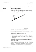
The operating current setting of the inverse time protection, or the lowest current
step of the definite time protection, must be defined so that the highest possible
load current does not cause protection operation. The protection reset current must
also be considered so that a short peak of overcurrent does not cause the operation
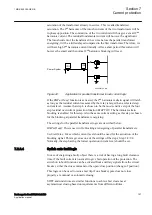
of a protection even when the overcurrent has ceased. This phenomenon is
described in Figure 

40

.

1MRK 505 388-UEN B

Section 7

Current protection

Busbar protection REB650 2.2 IEC

97

Application manual

Summary of Contents for REB650

Page 1: ...RELION 650 SERIES Busbar protection REB650 Version 2 2 Application manual...

Page 2: ......

Page 3: ...Document ID 1MRK 505 388 UEN Issued March 2018 Revision B Product version 2 2 Copyright 2017 ABB All rights reserved...

Page 4: ...rms of such license This product includes software developed by the OpenSSL Project for use in the OpenSSL Toolkit http www openssl org This product includes cryptographic software written developed b...

Page 5: ...roduct failure would create a risk for harm to property or persons including but not limited to personal injuries or death shall be the sole responsibility of the person or entity applying the equipme...

Page 6: ...d concerning electrical equipment for use within specified voltage limits Low voltage directive 2006 95 EC This conformity is the result of tests conducted by ABB in accordance with the product standa...

Page 7: ...on functions 24 Control and monitoring functions 25 Communication 28 Basic IED functions 30 Section 3 Configuration 33 Description of configuration REB650 33 Introduction 33 Description of A03 33 Sect...

Page 8: ...e open delta VT to the IED for low impedance earthed or solidly earthed power systems 60 Section 5 Local HMI 63 Display 64 LEDs 66 Keypad 67 Local HMI functionality 69 Protection and alarm indication...

Page 9: ...current protection NS4PTOC 111 Identification 111 Application 111 Setting guidelines 113 Settings for each step 113 Common settings for all steps 116 Thermal overload protection two time constants TRP...

Page 10: ...ion ROV2PTOV 139 Identification 139 Application 139 Setting guidelines 139 Equipment protection such as for motors generators reactors and transformersEquipment protection for transformers 140 Equipme...

Page 11: ...dentification 168 Application 168 Setting guidelines 168 Generic communication function for Double Point indication DPGAPC 169 Identification 169 Application 169 Setting guidelines 170 Single point ge...

Page 12: ...CALH 183 Identification 183 Application 183 Setting guidelines 184 Configurable logic blocks 184 Application 184 Setting guidelines 184 Configuration 184 Fixed signal function block FXDSIGN 185 Identi...

Page 13: ...ion 197 Application 197 Zero clamping 199 Setting guidelines 200 Setting examples 203 Gas medium supervision SSIMG 207 Identification 207 Application 207 Setting guidelines 208 Liquid medium supervisi...

Page 14: ...7 Pulse counter logic PCFCNT 227 Identification 227 Application 227 Setting guidelines 227 Function for energy calculation and demand handling ETPMMTR 228 Identification 228 Application 228 Setting gu...

Page 15: ...255 Application 255 MULTICMDRCV and MULTICMDSND 256 Identification 257 Application 257 Setting guidelines 257 SPA communication protocol 257 Application 257 Setting guidelines 258 IEC 60870 5 103 com...

Page 16: ...ock 3 phase 3PHSUM 276 Application 277 Setting guidelines 277 Global base values GBASVAL 277 Identification 277 Application 277 Setting guidelines 278 Signal matrix for binary inputs SMBI 278 Applicat...

Page 17: ...phase and residual overcurrent protection 298 Non directional inverse time delayed phase and residual overcurrent protection 299 Current transformer requirements for CTs according to other standards...

Page 18: ...12...

Page 19: ...an analogue signal which do not have corresponding primary quantity the 1 1 ratio shall be set for the used analogue inputs on the IED Example of such functions are HZPDIF ROTIPHIZ and STTIPHIZ 4 Para...

Page 20: ...ssioning Operation Maintenance Decommissioning Deinstalling disposal Application manual Operation manual Installation manual Engineering manual Communication protocol manual Cyber security deployment...

Page 21: ...he cause of a fault The application manual contains application descriptions and setting guidelines sorted per function The manual can be used to find out when and for what purpose a typical protectio...

Page 22: ...ering manual 1MRK 511 420 UEN Installation manual 1MRK 514 027 UEN Communication protocol manual DNP3 1MRK 511 413 UUS Communication protocol manual IEC 60870 5 103 1MRK 511 416 UEN Communication prot...

Page 23: ...rning related to the concept discussed in the text It might indicate the presence of a hazard which could result in corruption of software or damage to equipment or property The information icon alert...

Page 24: ...600 software the character after an input signal name indicates that the signal must be connected to another function block in the application configuration to achieve a valid application configuratio...

Page 25: ...R ETPMMTR FUFSPVC SDDRFUF FUFSPVC HZPDIF HZPDIF HZPDIF INDCALH INDCALH INDCALH ITBGAPC IB16FCVB ITBGAPC L4UFCNT L4UFCNT L4UFCNT LCPTTR LCPTTR LCPTTR LD0LLN0 LLN0 LLN0 LDLPSCH LDLPDIF LDLPSCH LFPTTR LF...

Page 26: ...SYNRSYN SLGAPC SLGGIO SLGAPC SMBRREC SMBRREC SMBRREC SMPPTRC SMPPTRC SMPPTRC SP16GAPC SP16GGIO SP16GAPC SPC8GAPC SPC8GGIO SPC8GAPC SPGAPC SPGGIO SPGAPC SSCBR SSCBR SSCBR SSIMG SSIMG SSIMG SSIML SSIML...

Page 27: ...WRNCALH WRNCALH ZCLCPSCH ZCLCPLAL ZCLCPSCH ZCPSCH ZCPSCH ZCPSCH ZCRWPSCH ZCRWPSCH ZCRWPSCH ZCVPSOF ZCVPSOF ZCVPSOF ZMFPDIS ZMFLLN0 PSFPDIS ZMFPDIS ZMFPTRC ZMMMXU PSFPDIS PSFPDIS ZMFPDIS ZMFPTRC ZMMMXU...

Page 28: ...22...

Page 29: ...ential current is connected to the IED via a high ohmic resistor In REB650 a current input is used for each phase and protection zone The package is configured and ready for direct use Analog inputs a...

Page 30: ...ample of quantities 2 number of basic instances 0 3 option quantities 3 A03 optional function included in packages A03 refer to ordering details IEC 61850 or function name ANSI Function description Bu...

Page 31: ...ng device via GOOSE 9 SLGAPC Logic rotating switch for function selection and LHMI presentation 15 VSGAPC Selector mini switch 30 DPGAPC Generic communication function for Double Point indication 16 S...

Page 32: ...onversion 18 ITBGAPC Integer to Boolean 16 conversion with Logic Node representation 16 TEIGAPC Elapsed time integrator with limit transgression and overflow supervision 12 INTCOMP Comparator for inte...

Page 33: ...ingle point indication 64 SP16GAPC Generic communication function for single point indication 16 inputs 16 MVGAPC Generic communication function for measured values 24 BINSTATREP Logical signal status...

Page 34: ...IEC 60870 5 103 for SLM 1 RS485PROT Operation selection for RS485 1 RS485GEN RS485 1 DNPGEN DNP3 0 communication general protocol 1 CHSERRS485 DNP3 0 for EIA 485 communication protocol 1 CH1TCP CH2TC...

Page 35: ...hysical device information 1 PCMACCS IED configuration protocol 1 SECALARM Component for mapping security events on protocols such as DNP3 and IEC103 1 FSTACCS Field service tool access 1 IEC 61850 9...

Page 36: ...puts SMBO Signal matrix for binary outputs SMAI1 SMAI12 Signal matrix for analog inputs 3PHSUM Summation block 3 phase ATHSTAT Authority status ATHCHCK Authority check AUTHMAN Authority management FTP...

Page 37: ...tion part for LHMI OPENCLOSE_LED LHMI LEDs for open and close keys GRP1_LED1 GRP1_LED15 GRP2_LED1 GRP2_LED15 GRP3_LED1 GRP3_LED15 Basic part for CP HW LED indication module 1MRK 505 388 UEN B Section...

Page 38: ...32...

Page 39: ...t All parameters should be verified by the customer since these are specific to the system object or application Optional functions and optional IO ordered will not be configured at delivery It should...

Page 40: ...94 1 0 SMP PTRC 94 1 0 SMP PTRC 94 1 0 CC PDSC 52PD PD CC RBRF 50BF 3I BF C MMXU MET I C MSQI MET Isqi FUF SPVC U I ETP MMTR MET W Varh EF4 PTOC 51N_67N 4 IN CV MMXN MET P Q NS4 PTOC 46I2 4 I2 OC4 PTO...

Page 41: ...fixed to zero degrees and remaining analog channel s phase angle information will be shown in relation to this analog input During testing and commissioning of the IED the reference channel can be ch...

Page 42: ...ee Figure 3 A positive value of current power and so on forward means that the quantity flows towards the object A negative value of current power and so on reverse means that the quantity flows away...

Page 43: ...FromObject IEC05000753 IEC05 000753 1 en Origin al 1 vsd Is Is Ip Ip Ip IED IED IEC05000753 V2 EN US Figure 4 Example how to set CTStarPoint parameters in the IED Figure 4 shows the normal case where...

Page 44: ...000460 V2 EN US Figure 5 Example how to set CTStarPoint parameters in the IED This example is similar to example 1 but here the transformer is feeding just one line and the line protection uses the sa...

Page 45: ...Reverse The direction Forward Reverse is related to the reference object that is the transformer in this case When a function is set to Reverse and shall protect an object in reverse direction it sha...

Page 46: ...ters in two ways The first solution will be to use busbar as a reference object In that case for all CT inputs marked with 1 in Figure 8 set CTStarPoint ToObject and for all CT inputs marked with 2 in...

Page 47: ...kings of CT terminals Where a is symbol and terminal marking used in this document Terminals marked with a square indicates the primary and secondary winding terminals with the same that is positive p...

Page 48: ...the actions which are needed to make this measurement available to the built in protection and control functions within the IED as well For correct terminal designations see the connection diagrams v...

Page 49: ...le for all built in protection and control functions within the IED which are connected to this preprocessing function block For this application most of the preprocessing settings can be left to the...

Page 50: ...the setting of the parameter CTStarPoint of the used current inputs on the TRM item 2 in Figure 11 and 10 CTprim 600A CTsec 5A CTStarPoint FromObject The ratio of the first two parameters is only use...

Page 51: ...l phase currents 3 Is the TRM where these current inputs are located It shall be noted that for all these current inputs the following setting values shall be entered CTprim 800A CTsec 1A CTStarPoint...

Page 52: ...ection and control functions within the IED which are connected to this preprocessing function block in the configuration tool For this application most of the preprocessing settings can be left to th...

Page 53: ...L2 IL3 IL3 IL1 1 2 3 4 IEC11000027 3 en vsdx SMAI2 BLOCK REVROT GRP2L1 GRP2L2 GRP2L3 GRP2N AI3P AI1 AI2 AI3 AI4 AIN IEC11000027 V3 EN US Figure 13 Delta DAB connected three phase CT set 1MRK 505 388 U...

Page 54: ...ter the connected analog inputs and calculate fundamental frequency phasors for all three input channels harmonic content for all three input channels positive negative and zero sequence quantities by...

Page 55: ...entered CTprim 800A CTsec 1A CTStarPoint ToObject ConnectionType Ph Ph It is important to notice the references in SMAI As inputs at Ph Ph are expected to be L1L2 L2L3 respectively L3L1 we need to til...

Page 56: ...oObject For connection b shown in Figure 15 CTprim 1000 A CTsec 1A CTStarPoint FromObject 3 shows the connection made in SMT tool which connect this CT input to the fourth input channel of the preproc...

Page 57: ...y make the protection scheme less sensitive however such measures are necessary in order to avoid possible problems with loss of the measurement accuracy in the IED Regardless of the applied relations...

Page 58: ...a square indicate the primary and secondary winding terminals with the same positive polarity b is the equivalent symbol and terminal marking used by IEC ANSI standard for phase to earth connected VTs...

Page 59: ...the built in protection and control functions within the IED For correct terminal designations see the connection diagrams valid for the delivered IED L1 IED L2 L3 66 3 110 3 kV V 1 3 2 66 3 110 3 kV...

Page 60: ...2 is the TRM where these three voltage inputs are located For these three voltage inputs the following setting values shall be entered VTprim 132 kV VTsec 110 V Inside the IED only the ratio of these...

Page 61: ...asors for the first three input channels channel one taken as reference for sequence quantities These calculated values are then available for all built in protection and control functions within the...

Page 62: ...econdary side of a phase to phase VT to the VT inputs on the IED 2 is the TRM where these three voltage inputs are located It shall be noted that for these three voltage inputs the following setting v...

Page 63: ...tings shall be set as shown here ConnectionType Ph Ph UBase 13 8 kV If frequency tracking and compensation is required this feature is typically required only for IEDs installed in the generating stat...

Page 64: ...601 4 en vsdx Not Used Not Used SMAI2 BLOCK REVROT GRP2L1 GRP2L2 GRP2L3 GRP2N AI3P AI1 AI2 AI3 AI4 AIN IEC06000601 V4 EN US Figure 20 Open delta connected VT in high impedance earthed power system Sec...

Page 65: ...oltage input to the fourth input channel of the preprocessing function block 5 5 is a Preprocessing block that has the task to digitally filter the connected analog input and calculate fundamental fre...

Page 66: ...Uo U EQUATION1926 V1 EN US Equation 7 The primary rated voltage of such VT is always equal to UPh E Therefore three series connected VT secondary windings will give the secondary voltage equal only to...

Page 67: ...Not Used Not Used SMAI2 BLOCK REVROT GRP2L1 GRP2L2 GRP2L3 GRP2N AI3P AI1 AI2 AI3 AI4 AIN 2 3 4 5 IEC06000602 V4 EN US Figure 21 Open delta connected VT in low impedance or solidly earthed power syste...

Page 68: ...rth input channel of the preprocessing function block 4 5 preprocessing block has a task to digitally filter the connected analog inputs and calculate fundamental frequency phasors for all four input...

Page 69: ...0239 V3 EN US Figure 22 Local human machine interface The LHMI of the IED contains the following elements Keypad Display LCD LED indicators Communication port for PCM600 1MRK 505 388 UEN B Section 5 L...

Page 70: ...iew depends on the character size and the view that is shown The display view is divided into four basic areas IEC15000270 1 en vsdx IEC15000270 V1 EN US Figure 23 Display layout 1 Path 2 Content 3 St...

Page 71: ...on LED pages are available IEC13000240 1 en vsd GUID 5157100F E8C0 4FAB B979 FD4A971475E3 V1 EN US Figure 25 Indication LED panel The function button and indication LED panels are not visible at the s...

Page 72: ...e LHMI or PCM600 Information panels for the indication LEDs are shown by pressing the Multipage button Pressing that button cycles through the three pages A lit or un acknowledged LED is indicated wit...

Page 73: ...e in different views or menus The push buttons are also used to acknowledge alarms reset indications provide help and switch between local and remote control mode The keypad also contains programmable...

Page 74: ...h object control navigation and command push buttons and RJ 45 communication port 1 5 Function button 6 Close 7 Open 8 Escape 9 Left 10 Down 11 Up 12 Right 13 Key 14 Enter 15 Remote Local 16 Uplink LE...

Page 75: ...supply voltage is disconnected On Normal operation Flashing Internal fault has occurred Table 7 Start LED yellow LED state Description Off Normal operation On A protection function has started and an...

Page 76: ...The indication has been acknowledged but the activation signal is still on LatchedAck S F sequence The activation signal is on or it is off but the indication has not been acknowledged LatchedReset S...

Page 77: ...RJ 45 connector 2 Green indicator LED The default IP address for the IED front port is 10 1 150 3 and the corresponding subnetwork mask is 255 255 254 0 It can be set through the local HMI path Main...

Page 78: ...72...

Page 79: ...fferential protection function HZPDIF can be used as Generator differential protection Reactor differential protection Busbar differential protection Autotransformer differential protection for common...

Page 80: ...ntial protection HZPDIF function 6 1 2 1 The basics of the high impedance principle SEMOD54734 153 v9 The high impedance differential protection principle has been used for many years and is well docu...

Page 81: ...y operation It should be remembered that the whole scheme its built in components and wiring must be adequately maintained throughout the lifetime of the equipment in order to be able to withstand the...

Page 82: ...tor Note that very high peak voltages can appear To prevent the risk of flashover in the circuit a voltage limiter must be included The voltage limiter is a voltage dependent resistor Metrosil The ext...

Page 83: ...mA Operating voltage U Trip Stabilizing resistor R1 ohms Operating current level 5 A Stabilizing resistor R1 ohms Operating current level 5 A Stabilizing resistor R1 ohms Operating current level 5 A 2...

Page 84: ...stor currents are resistive The current measurement is insensitive to DC component in fault current to allow the use of only the AC components of the fault current in the above calculations The voltag...

Page 85: ...UR c Internal faults UR Protected Object IEC05000427 2 en vsd IEC05000427 V2 EN US Figure 32 The high impedance principle for one phase with two current transformer inputs 1MRK 505 388 UEN B Section 6...

Page 86: ...three phase high impedance differential protection Typical CT connections for three phase high impedance differential protection scheme are shown in figure 33 L1 A L2 B L3 C Protected Object CT 1200...

Page 87: ...igh impedance differential protection HZPDIF GUID D68A237F 610C 4AF0 870F 273117F64D92 v10 Restricted earth fault protection is a typical application for 1Ph High impedance differential protection HZP...

Page 88: ...e differential function can be switched On or Off U Alarm Set the alarm level The sensitivity can roughly be calculated as a certain percentage of the selected Trip level A typical setting is 10 of U...

Page 89: ...overload the current input must be considered especially during the secondary testing 6 1 4 3 T feeder protection M16850 4 v7 In many busbar arrangements such as one and a half breaker ring breaker me...

Page 90: ...US 3 Id IEC05000739 2 en vsd IEC05000739 V2 EN US Figure 35 The protection scheme utilizing the high impedance function for the T feeder Section 6 1MRK 505 388 UEN B Differential protection 84 Busbar...

Page 91: ...mer ratio 2000 1 A CT Class 20 VA 5P20 Secondary resistance 6 2 ohms Cable loop resistance 100 m 2 5 mm2 one way gives 2 0 8 ohm at 75 C Max fault current Equal to switchgear rated fault current 40 kA...

Page 92: ...Figure 37 It can clearly be seen that the sensitivity is not so much influenced by the selected voltage level so a sufficient margin should be used The selection of the stabilizing resistor and the l...

Page 93: ...is helps in utilizing maximum CT capability minimize the secondary fault thereby reducing the stability voltage limit Another factor is that during internal faults the voltage developed across the sel...

Page 94: ...than 2 U Trip Check from the table of selected resistances the required series stabilizing resistor value to use Since this application requires good sensitivity select SeriesResistor 300 ohm which gi...

Page 95: ...his can be either another IED with the same HZPDIF function or be a check about the fault condition which is performed by an earth overcurrent function or neutral point voltage function For such cases...

Page 96: ...90...

Page 97: ...cuit protection of different kinds of equipment connected to the power system such as shunt capacitor banks shunt reactors motors and others Back up short circuit protection of power generators In man...

Page 98: ...he function Power transformers can have a large inrush current when being energized This phenomenon is due to saturation of the transformer magnetic core during parts of the period There is a risk tha...

Page 99: ...Off AngleRCA Protection characteristic angle set in degrees If the angle of the fault loop current has the angle RCA the direction to the fault is forward AngleROA Angle value given in degrees to defi...

Page 100: ...step M12982 19 v10 x means step 1 2 3 and 4 DirModex The directional mode of step x Possible settings are Off Non directional Forward Reverse Characteristx Selection of time characteristic for step x...

Page 101: ...setting If Ix is set outside Ix Max and Ix Min the closest of the limits to Ix is used by the function If Ix Max is smaller than Ix Min the limits are swapped tx Definite time delay for step x The def...

Page 102: ...cs In order to fully comply with the definition of the curve the setting parameter txMin shall be set to a value equal to the operating time of the selected inverse curve for twenty times the set curr...

Page 103: ...rvx These parameters are used by the customer to create the inverse reset time characteristic curve For more information refer to Technical manual HarmRestrainx Enables the block of step x from the ha...

Page 104: ...id for several years In most cases the setting values are updated once every five years or less often Investigate the maximum load current that the equipment on the line can withstand Study components...

Page 105: ...ach must be considered due to a possible DC component of the short circuit current The lowest current setting of the fastest stage can be written according to max 1 2 t sc high I k I EQUATION1265 V1 E...

Page 106: ...ctions in the radial network there has to be a minimum time difference Dt between the time delays of two protections To determine the shortest possible time difference the operation time of the protec...

Page 107: ...e 42 Sequence of events during fault where t 0 is when the fault occurs t t1 is when protection IED B1 and protection IED A1 start t t2 is when the trip signal from the overcurrent protection at IED B...

Page 108: ...ystem Some applications are Earth fault protection of feeders in effectively earthed distribution and subtransmission systems Normally these feeders have radial structure Back up earth fault protectio...

Page 109: ...is allowed to polarize can also be selected Choice of time characteristics There are several types of time characteristics available such as definite time delay and different types of inverse time cha...

Page 110: ...peration of the protection Therefore EF4PTOC has a possibility of second harmonic restrain if the level of 2nd harmonic current reaches a value above a set percent of the fundamental current 7 2 3 Set...

Page 111: ...e setting range is 180 to 180 polMethod Defines if the directional polarization is from Voltage 3U0 or U2 Current 3I0 ZNpol or 3I2 ZNpol where ZNpol is RNpol jXNpol or both currents and voltage Dual d...

Page 112: ...utput signals STFW and STRV can be used in a teleprotection scheme The appropriate signal should be configured to the communication scheme block 7 2 3 2 2nd harmonic restrain M15282 90 v6 If a power t...

Page 113: ...c restrain blocking is enabled for this step Also the same current setting as this step is chosen for the blocking at parallel transformer energizing The settings for the parallel transformer logic ar...

Page 114: ...g The setting range is 0 000 60 000 s in step of 0 001 s The default setting is 1 000 s ActUnderTime Describes the mode to activate the sensitive undertime function The function can be activated by Ci...

Page 115: ...uld only be changed if remote setting of operation current level INx is used The limits are used for decreasing the used range of the INx setting If INx is set outside INx Max and INx Min the closest...

Page 116: ...ary input signal ENMULTx is activated the current operation level is increased by this setting constant ResetTypeCrvx The reset of the delay timer can be made in different ways The possibilities are d...

Page 117: ...ial structure Back up earth fault and phase phase short circuit protection of transmission lines Sensitive earth fault protection of transmission lines NS4PTOC can have better sensitivity to detect re...

Page 118: ...d against each other should have the same time characteristic Therefore a wide range of standardized inverse time characteristics are available IEC and ANSI Table 15 Inverse time characteristics Curve...

Page 119: ...SVAL GlobalBaseSel Selects the global base value group used by the function to define IBase UBase and SBase as applicable GUID F7AA2194 4D1C 4475 8853 C7D064912614 v4 When inverse time overcurrent cha...

Page 120: ...start and the trip outputs kx Time multiplier for the dependent inverse characteristic IMinx Minimum operate current for step x in of IBase Set IMinx below Ix for every step to achieve ANSI reset cha...

Page 121: ...ANSI inverse time delay characteristics all three types of reset time characteristics are available instantaneous 1 IEC 2 set constant time reset and ANSI 3 current dependent reset time For IEC inver...

Page 122: ...an be found in the Technical Reference Manual 7 3 3 2 Common settings for all steps GUID A00A942B E760 42EE 8FEB F723426783F3 v1 x means step 1 2 3 and 4 AngleRCA Relay characteristic angle given in d...

Page 123: ...age of UBase I Dir Operate residual current level for directional comparison scheme The setting is given in of IBase The start forward or start reverse signals can be used in a communication scheme Th...

Page 124: ...thermal overload protection provides information and makes temporary overloading of transformers possible The permissible load level of a power transformer is highly dependent on the cooling system of...

Page 125: ...d SBase as applicable IRef Reference level of the current given in When the current is equal to IRef the final steady state heat content is equal to 1 It is suggested to give a setting corresponding t...

Page 126: ...he transformer has forced cooling FOA the measurement should be made both with and without the forced cooling in operation giving Tau2 and Tau1 The time constants can be changed if the current is high...

Page 127: ...hen the estimated heat content is below the set value This temperature value should be chosen below the alarm temperature ResLo is set in of the trip heat content level ThetaInit Heat content before a...

Page 128: ...te the operate time IRef 110 IBase1 110 of IB IBase2 120 of IB Tau1 150 min Tau2 90 min IHighTau1 110 of IB1 Tau1High 125 of tC1 ILowTau1 90 of IB1 Tau1Low 75 of tC1 IHighTau2 110 of IB2 Tau2High 115...

Page 129: ...9 where tlockout_release is the time to lockout release Qlockout_release is the lockout release level heat content ResLo operate Consider that the current heat content n is 2700000 and the cooling sys...

Page 130: ...set via the local HMI or PCM600 The following settings can be done for the breaker failure protection GlobalBaseSel Selects the global base value group used by the function to define IBase UBase and...

Page 131: ...s 1 out of 3 is sufficient For Contact operation means back up trip is done when circuit breaker is closed breaker position is used IP Current level for detection of breaker failure set in of IBase Th...

Page 132: ...pendent of re trip timer The minimum time delay for the re trip can be estimated as _ 2 1 cbopen BFP reset margin t t t t t EQUATION1430 V1 EN US Equation 30 where tcbopen is the maximum opening time...

Page 133: ...nctions tripping different back up circuit breakers tCBAlarm Time delay for alarm in case of indication of faulty circuit breaker There is a binary input CBFLT from the circuit breaker This signal is...

Page 134: ...CCPDSC will detect situation with deviating positions of the poles of the protected circuit breaker The protection has two different options to make this detection By connecting the auxiliary contact...

Page 135: ...monitor the function is activated only directly in connection to breaker open or close command during 200 ms In the alternative Continuous monitor function is continuously activated CurrUnsymLevel Un...

Page 136: ...130...

Page 137: ...ltage regulator or wrong settings under manual control symmetrical voltage decrease Overload symmetrical voltage decrease Short circuits often as phase to earth faults unsymmetrical voltage decrease U...

Page 138: ...3 1 Equipment protection such as for motors and generators M13851 50 v3 The setting must be below the lowest occurring normal voltage and above the lowest acceptable voltage for the equipment 8 1 3 2...

Page 139: ...t of 3 In most applications it is sufficient that one phase voltage is low to give operation If UV2PTUV shall be insensitive for single phase to earth faults 2 out of 3 can be chosen In subtransmissio...

Page 140: ...lock of trip Block all In case of a low voltage the undervoltage function can be blocked This function can be used to prevent function when the protected object is switched off If the parameter is set...

Page 141: ...n power system like metallic connection to a higher voltage level broken conductor falling down to a crossing overhead line transformer flash over fault from the high voltage winding to the low voltag...

Page 142: ...ion capacitors M13852 13 v1 High voltage will deteriorate the dielectricum and the insulation The setting has to be well above the highest occurring normal voltage and well below the highest acceptabl...

Page 143: ...v curve The choice is highly dependent of the protection application OpModen This parameter describes how many of the three measured voltages that should be above the set level to give operation The s...

Page 144: ...Crvn BCrvn CCrvn DCrvn PCrvn Parameters to set to create programmable under voltage inverse time characteristic Description of this can be found in the technical reference manual CrvSatn When the deno...

Page 145: ...stance the residual voltage will reach different values The highest residual voltage equal to three times the phase to earth voltage is achieved for a single phase to earth fault The residual voltage...

Page 146: ...ual voltage for the capacitor 8 3 3 3 Power supply quality M13853 15 v3 The setting must be above the highest occurring normal residual voltage and below the highest acceptable residual voltage due to...

Page 147: ...phase is indicated by voltage collapse in that phase The other healthy phase will still have normal phase to earth voltage The residual sum will have the same value as the remaining phase to earth vo...

Page 148: ...The setting parameters described below are identical for the two steps n step 1 and 2 Therefore the setting parameters are described only once OperationStepn This is to enable disable operation of st...

Page 149: ...DCrvn PCrvn Parameters for step n to set to create programmable undervoltage inverse time characteristic Description of this can be found in the technical reference manual CrvSatn Set tuning parameter...

Page 150: ...144...

Page 151: ...to the voltage instrument transformers and shall be equipped with auxiliary contacts that are wired to the IEDs Separate fuse failure monitoring IEDs or elements within the protection and monitoring...

Page 152: ...quence and delta algorithm are in percent of the base voltage and base current for the function Common base IED values for primary current IBase primary voltage UBase and primary power SBase are set i...

Page 153: ...rity of the fuse failure function OpMode can be selected to UZsIZs AND UNsINs which gives that both negative and zero sequence algorithms are activated and working in an AND condition that is both alg...

Page 154: ...ing normal operating conditions plus a margin of 10 20 IBase is the base current for the function according to the setting GlobalBaseSel 9 1 3 5 Delta U and delta I GUID 02336F26 98C0 419D 8759 45F5F1...

Page 155: ...tion for operation of the dead line detection is set by the parameters IDLD for the current threshold and UDLD for the voltage threshold Set the IDLD with a sufficient margin below the minimum expecte...

Page 156: ...150...

Page 157: ...lace selection and external or internal blockings The complete apparatus control function is not included in this product and the information below is included for understanding of the principle for t...

Page 158: ...supervision of operator place Command supervision Block deblock of operation Block deblock of updating of position indications Substitution of position indications Overriding of interlocking functions...

Page 159: ...receive for switching device GOOSEXLNRCV Proxy for signals from switching device via GOOSE XLNPROXY The extension of the signal flow and the usage of the GOOSE communication are shown in Figure 53 IE...

Page 160: ...control functions with XCBR and XSWI located in a breaker IED Control operation can be performed from the local IED HMI If users are defined in the IED then the local remote switch is under authority...

Page 161: ...3 4 5 6 PSTO All then it is no priority between operator places All operator places are allowed to operate According to IEC 61850 standard the orCat attribute in originator category are defined in Ta...

Page 162: ...also provides blocking functions that can be distributed to different apparatuses within the bay There are two different blocking alternatives Blocking of update of positions Blocking of commands IEC...

Page 163: ...be given The switch controller represents the content of the SCSWI logical node according to IEC 61850 with mandatory functionality 10 1 4 Switches SXCBR M16602 3 v7 Switches are functions used to cl...

Page 164: ...R or SXSWI function The command response functionality is dependent on the connection of the execution information XIN from the SCSWI function controlling the represented switch Otherwise the function...

Page 165: ...US Figure 55 Configuration with XLNPROXY and GOOSEXLNRCV where all the IEC 61850 modelled data is used including selection 1MRK 505 388 UEN B Section 10 Control Busbar protection REB650 2 2 IEC 159 A...

Page 166: ...itch to start moving it checks if the switch is blocked for the operation When the switch has started moving and no blocking condition has been detected XLNPROXY issues a response to the SCSWI functio...

Page 167: ...on The OPCAP input and output are used for the CBOpCap data of a XCBR respectively SwOpCap for a XSWI The interpretation for the command following is controlled through the setting SwitchType 10 1 6 I...

Page 168: ...open breaker with predefined switching conditions synchrocheck Also the case that one side is dead energizing check is included The Generic Automatic Process Control function GAPC handles generic com...

Page 169: ...ble open Open rel Close rel Open rel SMPPTRC Trip logic Position Pos from other bays Synchronizing OK Synchrocheck OK Start Synchronizing Synchronizing in progress SCILO Interlocking Enable open Enabl...

Page 170: ...ommand is desired the model direct control with normal security is used At control with enhanced security there is an additional supervision of the status value by the control object which means that...

Page 171: ...e Sel Op phase or only at operate Op phase 10 1 7 3 Switch SXCBR M16675 3 v8 tStartMove is the supervision time for the apparatus to start moving after a command execution is done from the SCSWI funct...

Page 172: ...and a cause code is given During the tIntermediate time the position indication is allowed to be in an intermediate 00 state When the time has expired the command supervision is reset and a cause cod...

Page 173: ...st be careful in coordinating the settings with the configuration if one sets the number of positions to x in settings for example there will be only the first x outputs available from the block in th...

Page 174: ...tput POSITION is an integer output showing the actual position as an integer number 0 3 where 0 MidPos 1 Open 2 Closed and 3 Error An example where VSGAPC is configured to switch Autorecloser on off f...

Page 175: ...pment or functions one must use other tools described in the Engineering manual and define which function block in which systems equipment or functions should receive this information More specificall...

Page 176: ...k is a collection of 8 single point commands that can be used for direct commands for example reset of LED s or putting IED in ChangeLock state from remote In this way simple commands can be sent dire...

Page 177: ...S function plays the same role as functions GOOSEBINRCV for IEC 61850 and MULTICMDRCV for LON AUTOBITS function block have 32 individual outputs which each can be mapped as a Binary Output point in DN...

Page 178: ...th the configuration logic circuits the user can govern pulses or steady output signals for control purposes within the IED or via binary outputs Figure 59 shows an application example of how the user...

Page 179: ...00207 V2 EN US Figure 60 Application example showing a logic diagram for control of built in functions Single command function SINGLESMD CMDOUTy OUTy Device 1 User defined conditions Configuration log...

Page 180: ...dependent of the values sent from the station level that is the operator station or remote control gateway Steady sets the outputs to a steady signal 0 or 1 depending on the values sent from the stati...

Page 181: ...faults 1ph 3ph operating mode Single phase tripping for single phase faults two phase tripping for two phase faults and three phase tripping for three phase faults 1ph 2ph 3ph operating mode If the O...

Page 182: ...tTripMin 150ms The typical connection is shown below in figure 62 BLOCK BLKLKOUT TRIN TRINL1 TRINL2 TRINL3 PSL1 PSL2 PSL3 1PTRZ 1PTREF P3PTR SETLKOUT RSTLKOUT STDIR TRIP SMPPTRC TRL1 TRL2 TRL3 TR1P T...

Page 183: ...n single phase tripping schemes are used a single phase autoreclosing attempt is expected to follow For cases where the autoreclosing is not in service or will not follow for some reason the input pre...

Page 184: ...ngle phase tripping application 11 1 2 3 Single two or three phase tripping M14828 15 v5 The single two three phase tripping mode provides single phase tripping for single phase faults two phase tripp...

Page 185: ...the input SETLKOUT will result in lock out This is normally the case for overhead line protection where most faults are transient Unsuccessful autoreclose and back up zone tripping can in such cases b...

Page 186: ...N REVN BLOCK START FW REV STL1 FWL1 REVL1 STL2 FWL2 REVL2 STL3 FWL3 REVL3 STDIR STARTCOMB STN FWN REVN STN FWN REVN PROTECTION 3 IEC16000180 2 en vsdx IEC16000180 V2 EN US Figure 64 Example of the con...

Page 187: ...and latches the TRIP related outputs The normal selection is Off AutoLock Sets the scheme for lock out Off only activates lock out through the input SETLKOUT On additionally allows lock out activatio...

Page 188: ...e activation conditions no longer are fulfilled It is only used in Steady mode When used for direct tripping of circuit breaker s the off delay time shall be set to at least 0 150 seconds in order to...

Page 189: ...ts according to the specific application needs 11 4 1 2 Setting guidelines GUID B08F2636 33DA 4937 92EB 1A8AC0909AB4 v2 OperationOn or Off 11 5 Logic for group indication INDCALH 11 5 1 Identification...

Page 190: ...guidelines GUID E6BD982D 9E47 4CC2 9666 6E5CABA414C0 v4 There are no settings for AND gates OR gates inverters or XOR gates For normal On Off delay and pulse timers the time delays and pulse lengths...

Page 191: ...e delays must be introduced into the logic schemes to prevent errors for example race between functions 11 7 Fixed signal function block FXDSIGN IP15080 1 v2 11 7 1 Identification SEMOD167904 2 v2 Fun...

Page 192: ...the neutral point is available This means that only two inputs are used Since all group connections are mandatory to be connected the third input needs to be connected to something which is the GRP_OF...

Page 193: ...for receiving up to 16 booleans input locally If the BLOCK input is activated it will freeze the output at the last value Values of each of the different OUTx from function block B16I for 1 x 16 The...

Page 194: ...le on the output OUT as a sum of the values of all the inputs INx that are activated OUT is an integer When all INx where 1 x 16 are activated that is Boolean 1 it corresponds to that integer 65535 is...

Page 195: ...teger output signals from one function to binary logical inputs to another function IB16 function does not have a logical node mapping The Boolean 16 to integer conversion function IB16 will transfer...

Page 196: ...s 65535 65535 is the highest boolean value that can be converted to an integer by the IB16 function block 11 11 Integer to Boolean 16 conversion with logic node representation ITBGAPC SEMOD158419 1 v3...

Page 197: ...UT4 BOOLEAN Output 4 8 0 OUT5 BOOLEAN Output 5 16 0 OUT6 BOOLEAN Output 6 32 0 OUT7 BOOLEAN Output 7 64 0 OUT8 BOOLEAN Output 8 128 0 OUT9 BOOLEAN Output 9 256 0 OUT10 BOOLEAN Output 10 512 0 OUT11 BO...

Page 198: ...values defined A resolution of 10 ms can be achieved when the settings are defined within the range 1 00 second tAlarm 99 999 99 seconds 1 00 second tWarning 99 999 99 seconds If the values are above...

Page 199: ...alues Signed Comparison is performed on signed values of input and reference values RefSource This setting is used to select the reference source between input and setting for comparison Input REF The...

Page 200: ...the system relative to each other or to a fixed value It is a basic arithmetic function that can be used for monitoring supervision interlocking and other logics 11 14 3 Setting guidelines GUID DE69F...

Page 201: ...example GUID E7070CF6 B44B 4799 BE18 5C75B9FE2A87 v2 Let us consider a comparison is to be done between current magnitudes in the range of 90 to 110 with nominal rating is 100 and the order is kA For...

Page 202: ...EqualBandHigh 5 0 of reference value EqualBandLow 5 0 of reference value Section 11 1MRK 505 388 UEN B Logic 196 Busbar protection REB650 2 2 IEC Application manual...

Page 203: ...US Voltage sequence component measurement VMSQI U1 U2 U0 SYMBOL TT V1 EN US Phase neutral voltage measurement VNMMXU U SYMBOL UU V1 EN US 12 1 2 Application SEMOD54488 4 v12 Measurement functions are...

Page 204: ...rvision can be used to report measured signal value to station level when change in measured value is above set threshold limit or time integral of all changes since the last time value updating excee...

Page 205: ...ons regarding any settings or parameters Zero clampings are also handled entirely by ZeroDb separately for each function s every output signal For example zero clamping of U12 is handled by UL12ZeroDb...

Page 206: ...r out of operation Off The following general settings can be set for the Measurement function CVMMXN PowAmpFact Amplitude factor to scale power calculations PowAngComp Angle compensation for phase shi...

Page 207: ...e for analog signal X This forms the maximum limit of the range XZeroDb Zero point clamping A signal value less than XZeroDb is forced to zero Observe the related zero point clamping settings in Setti...

Page 208: ...ngleRef defines the reference Calibration curves It is possible to calibrate the functions CVMMXN CMMXU VMMXU and VNMMXU to get class 0 5 presentations of currents voltages and powers This is accompli...

Page 209: ...pplication for a 400kV OHL SEMOD54481 12 v11 Single line diagram for this application is given in figure 69 400kV Busbar 400kV OHL P Q 1000 1 A IEC09000039 3 en vsdx IED kV 3 1 0 3 400 IEC09000039 1 E...

Page 210: ...required UGenZeroDb Zero point clamping in of Ubase 25 Set minimum voltage level to 25 Voltage below 25 will force S P and Q to zero IGenZeroDb Zero point clamping in of Ibase 3 Set minimum current l...

Page 211: ...ed value Comments IAmpComp5 Amplitude factor to calibrate current at 5 of Ir 0 00 IAmpComp30 Amplitude factor to calibrate current at 30 of Ir 0 00 IAmpComp100 Amplitude factor to calibrate current at...

Page 212: ...er as indicated in figure 70 it is necessary to do the following 1 Set correctly all CT and VT and phase angle reference channel PhaseAngleRef data using PCM600 for analog input channels 2 Connect in...

Page 213: ...to 3 UBase set in Global base Base setting for voltage level in kV 35 00 Set LV side rated phase to phase voltage IBase set in Global base Base setting for current level in A 495 Set transformer LV w...

Page 214: ...rature lockout condition in the circuit breaker tPressureAlarm This is used to set the time delay for a pressure alarm indication given in s tPressureLO This is used to set the time delay for a pressu...

Page 215: ...nes GUID 0C8E498B 2A65 44ED 91D6 53EC72F49222 v4 The parameters for Liquid medium supervision SSIML can be set via local HMI or Protection and Control Manager PCM600 Operation This is used to disable...

Page 216: ...es because there could be a number of abnormal operations or few operations with high level currents within the predetermined maintenance interval Hence condition based maintenance scheduling is an op...

Page 217: ...00 50000 20000 10000 2000 5000 1000 100 200 500 10 20 50 0 1 0 2 0 5 1 2 5 10 20 50 100 IEC12000623_1_en vsd IEC12000623 V1 EN US Figure 71 An example for estimating the remaining life of a circuit br...

Page 218: ...m the previous value The accumulated energy value can be reset to initial accumulation energy value by using the Reset accumulating energy input RSTIPOW Circuit breaker operation cycles Routine breake...

Page 219: ...LPH IPOWLOPH TRVTOPAL and TRVTCLAL signals are not used in SAM600 IO 12 4 3 1 Setting procedure on the IED GUID 4E895FEA 74BF 4B11 A239 0574F8FF5188 v5 The parameters for breaker monitoring SSCBR can...

Page 220: ...ssure lockout DirCoef Directional coefficient for circuit breaker life calculation RatedOperCurr Rated operating current of the circuit breaker RatedFltCurr Rated fault current of the circuit breaker...

Page 221: ...inputs can be set individually as NoEvents OnSet at pick up of the signal OnReset at drop out of the signal OnChange at both pick up and drop out of the signal AutoDetect the EVENT function makes the...

Page 222: ...improve existing equipment and so on This information can also be used in a longer perspective when planning for and designing new installations that is a disturbance recording could be a part of Func...

Page 223: ...00 It is possible to handle up to 40 analog and 352 binary signals either internal signals or signals coming from external inputs The binary signals are identical in all functions that is Disturbance...

Page 224: ...s Three LED indications placed above the LCD screen makes it possible to get quick status information about the IED Green LED Steady light In Service Flashing light Internal failure Dark No power supp...

Page 225: ...of recordings stored in the IED is 100 The oldest recording will be overwritten when a new recording arrives FIFO To be able to delete disturbance records Operation parameter has to be On The maximum...

Page 226: ...wer line In order to capture the new disturbance it is possible to allow retriggering PostRetrig On during the post fault time In this case a new complete recording will start and during a period run...

Page 227: ...d to trig the disturbance recorder If OperationM On waveform samples will also be recorded and reported in graph NomValueM Nominal value for input M OverTrigOpM UnderTrigOpM Over or Under trig operati...

Page 228: ...nsity of recording equipment in power systems is increasing since the number of modern IEDs where recorders are included is increasing This leads to a vast number of recordings at every single disturb...

Page 229: ...IEEE C37 2 device number Logical signal status report BINSTATREP 12 7 2 Application GUID F9D225B1 68F7 4D15 AA89 C9211B450D19 v3 The Logical signal status report BINSTATREP function makes it possible...

Page 230: ...e The four limit reach indication outputs can be utilized to initiate proceeding actions The output indicators remain high until the reset of the function It is also possible to initiate the counter f...

Page 231: ...line Settable time limits for warning and alarm are provided The time limit for overflow indication is fixed to 99999 9 hours At overflow the accumulated time resets and the accumulation starts from...

Page 232: ...226...

Page 233: ...the substation automation system or read via the station monitoring system as a service value When using IEC 61850 8 1 a scaled service value is available over the station bus The normal use for this...

Page 234: ...on the same board used for pulse counting 13 2 Function for energy calculation and demand handling ETPMMTR SEMOD153638 1 v2 13 2 1 Identification SEMOD175537 2 v4 Function description IEC 61850 ident...

Page 235: ...led with the pulse output setting values EAFAccPlsQty EARAccPlsQty ERFAccPlsQty and ERVAccPlsQty of the energy metering function and then the pulse counter can be set up to present the correct values...

Page 236: ...e MWh value in each pulse It should be selected together with the setting of the Pulse counter PCGGIO settings to give the correct total pulse value ERFAccPlsQty and ERVAccPlsQty gives the MVArh value...

Page 237: ...onfiguration tool ECT in PCM600 The access point is activated if the Operation checkbox is checked for the respective access point and a partial or common write to IED is performed To increase securit...

Page 238: ...n the other subnetwork By default this is set to 0 0 0 0 which means that no default gateway is selected ECT validates the entered value but the default gateway has to be in the same subnetwork as the...

Page 239: ...High availability Seamless Redundancy HSR provides redundant communication over station bus running the available communication protocols The redundant communication uses two Ethernet ports IEC0900075...

Page 240: ...ated when the parameter is set to PRP 0 PRP 1 or HSR The settings for the next access point will be hidden and PhyPortB will show the second port information Redundant communication is activated after...

Page 241: ...as Merging Units MU The rear access points are used for the communication The merging units MU are called so because they can gather analog values from one or more measuring transformers sample the d...

Page 242: ...oute specifies that when a package is sent to the destination device it should be sent through the selected router If no route is specified the source device will not find the destination device 14 4...

Page 243: ...tion between two or more intelligent electronic devices IEDs from one or several vendors to exchange information and to use it in the performance of their functions and for correct co operation GOOSE...

Page 244: ...em with IEC 61850 8 1 M16925 3 v4 Figure80 shows the GOOSE peer to peer communication Control Protection Control Protection Control and protection GOOSE en05000734 vsd Station HSI MicroSCADA Gateway I...

Page 245: ...ction for Single Point Value SPGAPC function is used to send one single logical output to other systems or equipment in the substation SP16GAPC can be used to send up to 16 single point values from th...

Page 246: ...s Application GUID 808177B7 02CA 40DF B41B 8B580E38478B v1 The GOOSE receive function blocks are used to receive subscribed data from the GOOSE protocol The validity of the data value is exposed as ou...

Page 247: ...t and the inaccuracy added by the merging unit must be coordinated with the requirement for the actual type of protection function Factors influencing the accuracy of the sampled values from the mergi...

Page 248: ...e merging units MU are called so because they can gather analog values from one or more measuring transformers sample the data and send the data over process bus to other clients or subscribers in the...

Page 249: ...lays IEC61850 8 1 en08000069 3 vsd IEC08000069 V2 EN US Figure 83 Example of a station configuration with the IED receiving analog values from both classical measuring transformers and merging units 1...

Page 250: ...eter is set to Block and the IED hardware time synchronization is lost or the synchronization to the MU time is lost the protection functions in the list 28 will be blocked due to conditional blocking...

Page 251: ...ked and processd normally DTT from the remote end is still processed IEC13000299 2 en vsd Direct transfer trip DTT local remote IED IED MU Not OK OK IEC13000299 V2 EN US Figure 85 MU failed mixed syst...

Page 252: ...failure protection CCRBRF PoleSlip Out of step protection PSPPPAM Breaker failure protection single phase version CCSRBRF Restricted earth fault protection low impedance REFPDIF Current circuit super...

Page 253: ...l TR1ATCC Generator stator overload protection GSPTTR Automatic voltage control for tapchanger parallel control TR8ATCC Directional Underpower protection GUPPDUP Thermal overload protection two time c...

Page 254: ...n quadrilateral for earth faults ZMMAPDIS Loss of voltage check LOVPTUV Fullscheme distance protection quadrilateral for earth faults ZMMPDIS Line differential protection 3 CT sets with inzone transfo...

Page 255: ...one MU is used as an analog source it is theoretically possible to do without time synchronization However this would mean that timestamps for analog and binary data events become uncorrelated If the...

Page 256: ...to PTP SyncLostMode set to Block to block protection functions if time synchronization is lost or set to BlockOnLostUTC if the protection functions are to be blocked when global common synchronizatio...

Page 257: ...S Figure 88 Setting example when MU is the synchronizing source Settings on the local HMI under Main menu Configuration Time Synchronization TIMESYNCHGEN 1 IEC61850 9 2 HwSyncSrc set to PPS as generat...

Page 258: ...TATION CLOCK IEC10000074 2 en Original vsd IEC10000074 V2 EN US Figure 89 Setting example with external synchronization Settings on the local HMI under Main menu Configuration Time Synchronization TIM...

Page 259: ...bled IEC UCA 61850 9 2LE Data MU IED IEC10000075 2 en Original vsd IEC10000075 V2 EN US Figure 90 Setting example without time synchronization It is also possible to use IEC UCA 61850 9 2LE communicat...

Page 260: ...is used to display the detailed quality of an IEC UCA 61850 9 2LE analog channel The component expands the channel quality output of a Merging Unit analog channel received in the IED as per the IEC 6...

Page 261: ...center and also from other IEDs via bay to bay horizontal communication For LON communication an SLM card should be ordered for the IEDs The fiber optic LON bus is implemented using either glass core...

Page 262: ...are module is used for control functions in the IEDs The module contains a process picture dialogues and a tool to generate a process database for the control application in MicroSCADA When using Micr...

Page 263: ...119915 1 v1 Settings M14789 4 v3 The parameters for the multiple command function are set via PCM600 The Mode setting sets the outputs to either a Steady or Pulsed mode 15 5 SPA communication protocol...

Page 264: ...nciple where the IED is a slave and the PC is the master Only one master can be applied on each fiber optic loop A program is required in the master computer for interpretation of the SPA bus codes an...

Page 265: ...different communication speeds are used in the same fiber optical loop or RS485 network take this into account when making the communication setup in the communication master the PC With local fiber...

Page 266: ...it RTU connected to the Communication and processing module the only hardware needed is optical fibers and an opto electrical converter for the PC RTU or a RS 485 connection depending on the used IED...

Page 267: ...r the PC RTU PC RTU Commands M17109 62 v4 The commands defined in the IEC 60870 5 103 protocol are represented in dedicated function blocks These blocks have output signals for all available commands...

Page 268: ...INFORMATION NUMBER parameter for each input signal Supervision indications in monitor direction Function block with defined functions for supervision indications in monitor direction I103Superv This b...

Page 269: ...ported when the fault locator function is included in the IED Disturbance recordings M17109 111 v9 The transfer functionality is based on the Disturbance recorder function The analog and binary signal...

Page 270: ...u Configuration Communication Station Communication IEC60870 5 103 config selector SlaveAddress BaudRate RevPolarity optical channel only CycMeasRepTime MasterTimeDomain TimeSyncMode EvalTimeAccuracy...

Page 271: ...lue delivered All GI data from a single block will come from the same cycle If EventRepMode HiPriSpont spontaneous events will be delivered prior to GI event To prevent old GI data from being delivere...

Page 272: ...rs on the disturbance recorder for each input The user must set these parameters to whatever he connects to the corresponding input Refer to description of Main Function type set on the local HMI Reco...

Page 273: ...on and information types M17109 145 v7 Product type IEC103mainFunType value Comment REL 128 Compatible range REC 242 Private range use default RED 192 Compatible range RET 176 Compatible range REB 207...

Page 274: ...power as specified in standard For more information refer to IEC standard IEC 60870 5 103 15 7 DNP3 Communication protocol 15 7 1 Application GUID EF1F0C38 9FF6 4683 8B10 AAA372D42185 v1 For more inf...

Page 275: ...he included self supervision with internal event list function block provides good supervision of the IED The fault signals make it easier to analyze and locate a fault Both hardware and software supe...

Page 276: ...B48775D0 ACF0 49C6 A7F6 69AF37F1C68F v1 16 3 1 Application GUID 51EEC9C7 8ECF 4546 BC26 326861654340 v4 Change lock function CHNGLCK is used to block further changes to the IED configuration once the...

Page 277: ...load that can be produced by Ethernet network traffic on the IED The communication facilities must not be allowed to compromise the primary functionality of the device All inbound network traffic wil...

Page 278: ...272...

Page 279: ...changeable data that uniquely identifies the IED Product information data is visible on the local HMI under Main menu Diagnostics IED status Product identifiers and under Main menu Diagnostics IED Sta...

Page 280: ...atus Product identifiers Firmware version numbers run independently from the release production numbers For every release number there can be one or more firmware versions depending on the small issue...

Page 281: ...etting groups IP1745 1 v1 17 4 1 Application M12007 6 v10 Six sets of settings are available to optimize IED operation for different power system conditions By creating and switching between fine tune...

Page 282: ...Only the selected number of setting groups will be available in the Parameter Setting tool PST for activation with the ActiveGroup function block 17 5 Rated system frequency PRIMVAL IP15064 1 v2 17 5...

Page 283: ...nominal system frequency ExternalDFTRef This setting means that the DFT samples per cycle adaptive DFT will be controlled by SMAI1 SPFCOUT FreqMeasMinVal The minimum value of the voltage for which th...

Page 284: ...e functions throughout the IED typically SBase 3 UBase IBase 17 8 Signal matrix for binary inputs SMBI SEMOD55793 1 v2 17 8 1 Application M15310 3 v2 The Signal matrix for binary inputs function SMBI...

Page 285: ...2 Frequency values GUID B494B93C B5AA 4FD6 8080 8611C34C2AD8 v5 The SMAI function includes a functionality based on the level of positive sequence voltage MinValFreqMeas to validate if the frequency m...

Page 286: ...rotection SAPFRC due to that all other information except frequency and positive sequence voltage might be wrongly calculated 17 10 3 Setting guidelines GUID C8D6C88B 87C6 44C1 804B CF1594365EE6 v8 Th...

Page 287: ...3Ph N negation means rotation with 180 of the vectors GlobalBaseSel Selects the global base value group used by the function to define IBase UBase and SBase MinValFreqMeas The minimum value of the vol...

Page 288: ...MAI5 29 5 SMAI6 30 6 SMAI7 31 7 SMAI8 32 8 SMAI9 33 9 SMAI10 34 10 SMAI11 35 11 SMAI12 36 12 Task time group 3 AdDFTRefCh7 AdDFTRefCh4 IEC07000197 V2 EN US Figure 98 Twelve SMAI instances are grouped...

Page 289: ...nce i e frequency tracking master must be a voltage type Observe that positive sequence voltage is used for the frequency tracking feature For task time group 1 this gives the following settings see F...

Page 290: ...ltage type Observe that positive sequence voltage is used for the frequency tracking feature For task time group 1 this gives the following settings see Figure 98 for numbering SMAI1 1 SMAI12 12 DFTRe...

Page 291: ...on protocol manual IEC 61850 Edition 1 and Edition 2 There is no setting in PCM600 via PST for the TESTMODE function block To be able to set the function block TESTMODE remotely the setting via path o...

Page 292: ...icate the abnormal operation of the IED The IEC 61850 7 4 gives a detailed overview over all aspects of the test mode and other states of mode and behavior The status of a function block behavior Beh...

Page 293: ...ults Without time synchronization only the events within one IED can be compared with each other With time synchronization events and disturbances within the whole network can be compared and evaluate...

Page 294: ...ation 17 12 2 1 System time M11348 119 v6 The time is set with years month day hour minute second and millisecond 17 12 2 2 Synchronization M11348 143 v5 The setting parameters for the real time clock...

Page 295: ...on Time Protocol PTP is enabled disabled using the Ethernet configuration tool ECT in PCM600 PTP can be set to On Off or Slave only When set to Slave only the IED is connected to the PTP group and wil...

Page 296: ...system Figure 102 describes an example system The REC and REL are both using the 9 2 stream from the SAM600 and gets its synch from the GPS Moreover the REL and REC both acts as a boundary clock to pr...

Page 297: ...well as sync to the merging unit If synchronization of the IED and the merging unit is based on GPS set the parameter LostSyncMode to BlockOnLostUTC in order to provide a block of protection functions...

Page 298: ...292...

Page 299: ...These types are related to the design of the iron core and the presence of airgaps Airgaps affects the properties of the remanent flux The following three different types of protection CTs have been...

Page 300: ...gives a remanent flux higher than 80 of the saturation flux The High Remanence HR type is a CT with closed iron core for example protection classes TPX P PX according to IEC class C K according to AN...

Page 301: ...erformed in our network simulator The current transformer models are representative for current transformers of high remanence and low remanence type The results may not always be valid for non remane...

Page 302: ...aximum fault current for the relevant fault position should be used and therefore both fault types have to be considered 18 1 4 Secondary wire resistance and additional load M11614 3 v1 M11614 4 v4 Th...

Page 303: ...rmers with less accuracy are used it is advisable to check the actual unwanted residual current during the commissioning 18 1 6 Rated equivalent secondary e m f requirements SEMOD53723 1 v1 M11616 3 v...

Page 304: ...protection M11622 3 v5 The CTs must have a rated equivalent limiting secondary e m f Eal that is larger than or equal to the required rated equivalent limiting secondary e m f Ealreq below sr R al alr...

Page 305: ...Ipr The rated primary CT current A Isr The rated secondary CT current A Ir The rated current of the protection IED A Rct The secondary resistance of the CT W RL The resistance of the secondary cable...

Page 306: ...18 1 7 2 Current transformers according to IEC 61869 2 class PX PXR and old IEC 60044 6 class TPS and old British Standard class X M11623 14 v5 CTs according to these classes are specified approximat...

Page 307: ...f the corresponding Eal according to IEC 61869 2 Therefore the CTs according to ANSI IEEE must have a knee point voltage UkneeANSI that fulfills the following kneeANSI alreq V 0 75 maximum of E EQUATI...

Page 308: ...66590 11 v5 The merging units that supply the IED with measured values via the process bus must fulfill the IEC UCA 61850 9 2LE standard This part of the IEC 61850 is specifying Communication Service...

Page 309: ...rom the merging unit are for example anti aliasing filters frequency range step response truncating A D conversion inaccuracy time tagging accuracy etc In principle the accuracy of the current and vol...

Page 310: ...304...

Page 311: ...American Wire Gauge standard BBP Busbar protection BFOC 2 5 Bayonet fiber optic connector BFP Breaker failure protection BI Binary input BIM Binary input module BOM Binary output module BOS Binary out...

Page 312: ...isturbance recorder according to IEEE ANSI C37 111 1999 IEC 60255 24 Contra directional Way of transmitting G 703 over a balanced line Involves four twisted pairs two of which are used for transmittin...

Page 313: ...performance architecture ESD Electrostatic discharge F SMA Type of optical fiber connector FAN Fault number FCB Flow control bit Frame count bit FOX 20 Modular 20 channel telecommunication system for...

Page 314: ...e current transformers for transient performance IEC 60870 5 103 Communication standard for protection equipment A serial master slave protocol for point to point communication IEC 61850 Substation au...

Page 315: ...gmentation and reassembly through the data link layer 2 Ingression protection according to IEC 60529 IP 20 Ingression protection according to IEC 60529 level 20 IP 40 Ingression protection according t...

Page 316: ...ulse code modulation PCM600 Protection and control IED manager PC MIP Mezzanine card standard PELV circuit Protected Extra Low Voltage circuit type according to IEC60255 27 PMC PCI Mezzanine card POR...

Page 317: ...tion module SMA connector Subminiature version A A threaded connector with constant impedance SMT Signal matrix tool within PCM600 SMS Station monitoring system SNTP Simple network time protocol is us...

Page 318: ...suitable for further signal processing TYP Type identification UMT User management tool Underreach A term used to describe how the relay behaves during a fault condition For example a distance relay...

Page 319: ...V Undervoltage WEI Weak end infeed logic VT Voltage transformer 3IO Three times zero sequence current Often referred to as the residual or the earth fault current 3UO Three times the zero sequence vol...

Page 320: ...314...

Page 321: ...315...

Page 322: ...AB Grid Automation Products 721 59 V ster s Sweden Phone 46 0 21 32 50 00 abb com protection control Copyright 2017 ABB All rights reserved Specifications subject to change without notice 1MRK 505 388...

Reviews: