


The SESRSYN and connected SMAI function block instances must have
the same cycle time in the application configuration.
10.1.3.1
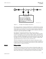
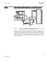
Single circuit breaker with single busbar
Line
Bus 1
Fuse
VT
ANSI11000164_2_en.vsd
VBus
VLine
Fuse
VT
SMAI
SMAI
GRP_OFF
SESRSYN (25)
V3PB1*
V3PB2*
V3PL1*
V3PL2*
BLOCK
BLKSYNCH
BLKSC
BLKENERG
BUS1_OP
BUS1_CL
BUS2_OP
BUS2_CL
LINE1_OP
LINE1_CL
LINE2_OP
LINE2_CL
VB1OK
VB1FF
VB2OK
VB2FF
VL1OK
VL1FF
VL2OK
VL2FF
STARTSYN
TSTSYNCH
TSTSC
TSTENERG
AENMODE
MENMODE
SYNOK
AUTOSYOK
AUTOENOK
MANSYOK
MANENOK
TSTSYNOK
TSTAUTSY
TSTMANSY
TSTENOK
VSELFAIL
B1SEL
B2SEL
L1SEL
L2SEL
SYNPROGR
SYNFAIL
FRDIFSYN
FRDERIVA
VOKSC
VDIFFSC
FRDIFFA
PHDIFFA
FRDIFFM
PHDIFFM
INADVCLS
VDIFFME
FRDIFFME
PHDIFFME
Vbus
VLine
MODEAEN
MODEMEN
189
BKR1
52
ANSI11000164 V2 EN
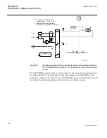
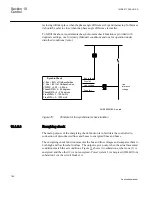
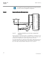
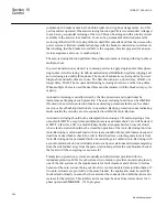
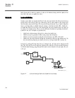
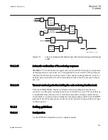
Figure 73:
Connection of SESRSYN (25) function block in a single busbar
arrangement
illustrates connection principles. For the SESRSYN (25) function there is one
voltage transformer on each side of the circuit breaker. The voltage transformer circuit
connections are straightforward; no special voltage selection is necessary.
The voltage from busbar VT is connected to V3PB1 and the voltage from the line VT is
connected to V3PL1. The positions of the VT fuses shall also be connected as shown
above. The voltage selection parameter
CBConfig
is set to
No voltage sel
.
Section 10
1MRK 511 286-UUS A
Control
190
Application manual
Summary of Contents for REC650 ANSI
Page 1: ...Relion 650 series Bay control REC650 ANSI Application manual...
Page 2: ......
Page 26: ...20...
Page 66: ...Section 3 1MRK 511 286 UUS A REC650 setting examples 60 Application manual...
Page 71: ...IED IED ANSI05000460 V2 EN 1MRK 511 286 UUS A Section 4 Analog inputs 65 Application manual...
Page 82: ...76...
Page 92: ...86...
Page 170: ...164...
Page 176: ...170...
Page 274: ...268...
Page 288: ...282...
Page 350: ...344...
Page 369: ...363...


