background image

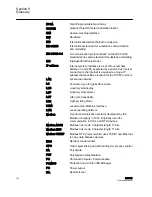
FPGA

Field Programmable Gate Array

GOOSE

Generic Object Oriented Substation Event

HMI

Human-machine interface

HW

Hardware

IEC

International Electrotechnical Commission

IEC 61850

International standard for substation communication

and modelling.

IEC 61850-8-1

A communication protocol based on the IEC 61850

standard series and a standard for substation modelling.

IED

Intelligent Electronic Device

IP address

Internet protocol address is a set of four numbers

between 0 and 255, separated by periods. Each server

connected to the Internet is assigned a unique IP

address that specifies a location for the TCP/IP protocol.

LAN

Local area network

LC

Connector type for glass fibre cable.

LCD

Liquid crystal display

LCP

Liquid crystal polymer

LCT

Life cycle traceability

LED

Light-emitting diode

LHMI

Local Human-Machine Interface

LON

Local operating network

Modbus

A serial communication protocol developed by the

Modicon company in 1979. Originally used for

communication in PLCs and RTU devices.

Modbus ASCII

Modbus link mode. Character length 10 bits.

Modbus RTU

Modbus link mode. Character length 11 bits.

Modbus TCP/IP

Modbus RTU protocol which uses TCP/IP and Ethernet

to carry data between devices.

NCC

Network control center

OPC

OLE (object linking and embedding) for process control

PA

Polyamide

PBT

Polybutylene terephthalate

PC

Personal Computer; Polycarbonate

PCM600

Protection and Control IED Manager

PO

Power output

R/L

Remote/Local

Section 9

Glossary

104

RED615

Operation Manual

Summary of Contents for RED615 ANSI

Page 1: ...Operation Manual Line Differential Protection and Control RED615...

Page 2: ......

Page 3: ...Document ID 1MRS756499 Issued 03 10 2008 Revision A Product version 1 1 Copyright 2008 ABB All rights reserved...

Page 4: ...used copied or disclosed only in accordance with the terms of such license Trademarks ABB is a registered trademark of ABB Group All other brand or product names mentioned in this document may be tra...

Page 5: ...roduct failure would create a risk for harm to property or persons including but not limited to personal injuries or death shall be the sole responsibility of the person or entity applying the equipme...

Page 6: ...quipment for use within specified voltage limits Low voltage directive 2006 95 EC This conformity is the result of a test conducted by ABB in accordance with Article 10 of the directive in agreement w...

Page 7: ...llation National and local electrical safety regulations must always be followed The frame of the device has to be carefully earthed When the plug in unit has been detached from the case do not touch...

Page 8: ......

Page 9: ...of the IED 13 Section 3 RED615 overview 15 Overview 15 Product version history 15 Operation functionality 15 Standard configurations 15 Optional functions 16 Physical hardware 16 LHMI 18 LCD 18 LEDs 2...

Page 10: ...lues 37 Committing settings 37 Clearing and acknowledging 38 Using LHMI help 38 Using WHMI 39 Logging in 39 Logging out 39 Identifying the device 41 Navigating in the menu 42 Menu structure 43 Showing...

Page 11: ...itoring disturbance recorder data 67 Controlling and uploading disturbance recorder data 68 Monitoring fault records 68 Monitoring events 69 Remote monitoring 69 Operating IED remotely 69 Controlling...

Page 12: ...nary output circuits 85 Authorizations 85 User authorization 85 Using PCM600 86 Setting communication between IEDs and PCM600 86 Communication options 86 Setting communication parameters 87 Setting IE...

Page 13: ...ABB Product Data Registration 100 Section 9 Glossary 103 Table of contents RED615 5 Operation Manual...

Page 14: ...6...

Page 15: ...iew calculated and measured network data in order to determine the cause of a fault 1 2 Intended audience This manual addresses the operator who operates the IED on a daily basis The operator must be...

Page 16: ...gineering Manual contains instructions on how to engineer the IEDs The manual provides instructions on how to use the different tools for IED engineering It also includes instructions on how to handle...

Page 17: ...descriptions and lists function blocks logic diagrams input and output signals setting parameters and technical data sorted per function The manual can be used as a technical reference during the eng...

Page 18: ...injury The caution icon indicates important information or warning related to the concept discussed in the text It might indicate the presence of a hazard which could result in corruption of software...

Page 19: ...put messages and monitored data names are shown in Courier font for example When the function starts the START output is set to TRUE 1 4 3 Functions codes and symbols Table 1 Functions included in the...

Page 20: ...C 60617 ANSI Trip circuit supervision TCSSCBR1 TCS TCM Current circuit supervision CCRDIF1 MCS 3I MCS 3I Protection communication supervision PCSRTPC1 PCS PCS Section 1 1MRS756499 A Introduction 12 RE...

Page 21: ...sured with extensive testing during the design and manufacturing processes Moreover long life time is supported by maintenance and repair services as well as by the availability of spare parts Design...

Page 22: ...c plates parts and screws Steel Plastic parts PC1 LCP2 Electronics plug in module Various Plug in unit Electronics plug in modules Various Electronics LHMI module Various Plastic parts PC PBT3 LCP PA4...

Page 23: ...the line differential main protection The IED is adapted for the protection of overhead line and cable feeders in isolated neutral resistance earthed compensated impedance earthed and solidly earthed...

Page 24: ...current detection Binary signal transfer Control Circuit breaker control with interlocking Supervision and Monitoring Trip circuit supervision of two trip circuits Local and remote phase currents pro...

Page 25: ...ts Case Optional BI O module slot X130 6 BIs 3 SO contacts AI module interface connectors Auxiliary power binary output module interface connectors BI O module interface connectors Communication modul...

Page 26: ...Communication port The LHMI is used for setting monitoring and controlling 3 5 1 LCD The LHMI includes a graphical LCD that supports two character sizes The character size depends on the selected lan...

Page 27: ...ows the current action or user level Current action is indicated by the following characters U Font Firmware is being updated S Parameters are being stored Warning and or indication Current user level...

Page 28: ...uttons you can give open or close commands to one primary object for example a circuit breaker disconnector or switch The push buttons are also used to acknowledge alarms reset indications provide hel...

Page 29: ...aving setting mode without saving the values Cancelling certain actions Adjusting the display contrast in combination with or Changing the language in combination with Running the display test in comb...

Page 30: ...rotection and alarm indication Protection indicators Protection indicator LEDs are called Ready Start and Trip Table 8 Ready LED LED state Description Off Auxiliary supply voltage is disconnected On N...

Page 31: ...ed Latched blinking mode alarm is still on but has been acknowledged Blinking Non latched blinking mode alarm is still on Latched blinking mode alarm is still on or it is off but has not been acknowle...

Page 32: ...the computer The fixed IP address for the front port is 192 168 0 254 3 6 WHMI The WHMI enables the user to access the IED via a web browser WHMI is disabled by default To enable the WHMI select Main...

Page 33: ...1 Command buttons Command buttons can be used to edit parameters and control information via the WHMI Table 12 Command buttons Name Description Preventing automatic logout Enabling parameter editing...

Page 34: ...Configuration Authorization WHMI always requires authentication Table 13 Predefined user categories Username User rights VIEWER Read only access OPERATOR Selecting remote or local state with only loc...

Page 35: ...nication connectors except for the front port connector are placed on integrated optional communication modules The IED can be connected to Ethernet based communication systems via theRJ 45 connector...

Page 36: ...ch as data format unit setting range visibility and access rights The description texts can be translated into other languages as well Software components that adapt the IED specific interfaces to the...

Page 37: ...ord authorization select Main Menu Configuration Authorization Local override Set the parameter to False 4 1 1 Logging in 1 Press any key except for to activate the login procedure 2 Press or to selec...

Page 38: ...level you are logged into shows on the LCD s upper right corner in the icon area 4 1 2 Logging out 1 Press 2 To confirm logout select Yes and press To cancel logout press 4 1 3 Turning display backli...

Page 39: ...rol operations are possible only from a higher level that is from a control center Press for two seconds When the L LED is lit local control is enabled and remote control disabled When the R LED is li...

Page 40: ...ss simultaneously and To decrease the contrast press simultaneously and The selected contrast value is stored in the non volatile memory if you are logged in and authorized to control the IED After an...

Page 41: ...s are changed With the LHMI the change takes effect immediately 4 1 9 Navigating in the menu Navigate the menus and change the display views on the screen with the keypad To move to the Main Menu or d...

Page 42: ...wards press To jump from the last row to the first row press again Press to jump from the first row to the last row To scroll parameter names and values that do not fit the screen press Press once to...

Page 43: ...lternatives in the selected setting group 4 1 11 Editing values You must be logged in and authorized to edit values 4 1 11 1 Editing numerical values 1 Select Main Menu Settings and then a setting Whe...

Page 44: ...or maximum value select the arrow symbol in front of the value To set the value to the maximum press To set the value to the minimum press A070756 V3 EN Figure 16 Arrow symbol is active the value is s...

Page 45: ...e parameter specific order 4 1 12 Committing settings Editable values are stored either in RAM or in non volatile flash memory Values stored in flash memory are in effect also after reboot Some parame...

Page 46: ...tched outputs as well as registers and recordings Press the Clear button to activate a selection menu where you can choose which clearance or reset function you want to make Events and alarms assigned...

Page 47: ...ng to a WHMI page you are redirected to the log in page With authorization you are redirected to the startup page 4 2 1 Logging in 1 Enter the username with capital letters 2 Enter the password 3 Clic...

Page 48: ...GUID D0ACBF32 78F1 458C 853A DAAA6E80E006 V2 EN Figure 21 Session timeout Section 4 1MRS756499 A Using HMI locally or via web interface 40 RED615 Operation Manual...

Page 49: ...189 A590 E8A60AF0FEB0 V2 EN Figure 22 WHMI logout 4 2 3 Identifying the device The IED information includes detailed information about the device such as revision and serial number 1MRS756499 A Sectio...

Page 50: ...he application configuration The Alarms view shows the status of alarm LEDs The Phasor diagrams view shows phasor diagrams The Parameter list view shows all parameters The WHMI settings view contains...

Page 51: ...s main groups which are divided further into more detailed submenus Language Monitoring Settings Configuration Tests Information Clear Disturbance records Events Measurements 4 2 5 Showing all paramet...

Page 52: ...9249 778C 416F BCFF 767F1E979D27 V3 EN Figure 25 Show all parameters 2 Click Print to print out all parameters on paper Section 4 1MRS756499 A Using HMI locally or via web interface 44 RED615 Operatio...

Page 53: ...t 4 2 6 Editing values 1 Click the menu in the WHMI tree 2 Click the submenu to see function blocks 3 Click a function block to see the setting values 4 Click Enable Write Some parameters for example...

Page 54: ...able writing to edit a value The selected setting group is shown in the Setting Group drop down box The active setting group is indicated with an asterisk 5 Edit the value Section 4 1MRS756499 A Using...

Page 55: ...e entered value is within the accepted value range the selection is highlighted in green If the value is out of range the row is highlighted in red and a warning dialog box appears A070934 V3 EN Figur...

Page 56: ...in RAM or in non volatile flash memory Values stored in flash memory are in effect also after reboot Some parameters have an edit copy If editing is cancelled the values with an edit copy are immediat...

Page 57: ...ues to the flash memory Click Reject to cancel saving settings If the parameter has an edit copy the original parameter value is restored If the parameter does not have an edit copy the edited paramet...

Page 58: ...only write values to the IED and then reboot the old values will resume in the IED as active values and the new values are lost 4 2 8 Clearing and acknowledging Reset acknowledge or clear all messages...

Page 59: ...N Figure 33 Selecting clear menu 2 Click Enable write 3 In the New Value box click True to select the item to be cleared 4 Click Write to IED 5 Click Reject 1MRS756499 A Section 4 Using HMI locally or...

Page 60: ...and LEDs 4 2 9 Selecting alarm view Alarm view shows the status of alarm LEDs These are the same LEDs that are located on the upper right side of the LHMI panel Click Alarms in the menu bar Section 4...

Page 61: ...e 35 Monitoring alarms 4 2 10 Selecting event view The event view contains a list of events produced by the application configuration 1 Click Events in the menu bar 1MRS756499 A Section 4 Using HMI lo...

Page 62: ...rmat The CSV file can be opened with a spreadsheet program such as OpenOffice org Calc or Microsoft Excel 3 Click Clear events to clear all events from the IED 4 2 11 Selecting phasor diagrams 1 Click...

Page 63: ...high degrees of load currents 2 Toggle the diagram visibility by selecting it from the drop down menu GUID 01FF8E6C 8FC4 47AE 8926 83C1B4B38D8D V3 EN Figure 38 Toggling the diagram visibility 1MRS7564...

Page 64: ...y changing the zoom value GUID BF7CF464 ACFC 4130 B823 A0996367B6AE V3 EN Figure 39 Zooming the diagram 4 Click Freeze to stop updating the phasor diagram No updates will appear in the diagram Section...

Page 65: ...value is too high Install an SVG plugin to view the phasor diagrams 4 2 12 Using WHMI help The context sensitive WHMI help provides information for example of a single parameter 1 Click The help dial...

Page 66: ...D2BEFF5 AF4C 4AFF ADFA C005A8B355ED V3 EN Figure 41 Clicking the help button 2 To close the help dialog box click OK Section 4 1MRS756499 A Using HMI locally or via web interface 58 RED615 Operation M...

Page 67: ...test you can analyze the results 5 2 Disturbance case operation The IED is designed to identify and indicate several types of disturbances The main purpose of a protective IED is to identify power sys...

Page 68: ...blinking Protection function blocked Trip LED Red steady Protections operated Ready LED Green blinking Internal faults Further actions to be taken to identify the disturbance Analyzing disturbance rec...

Page 69: ...l the recorded data from the IED before you reset the tripping and IED lockout functions 5 2 4 Disturbance recording triggering Disturbance recordings are normally triggered by IED applications when t...

Page 70: ...s need to be calculated according to the electrical network conditions and the electrical characteristics of the protected equipment The IED s settings need to be verified before the IED is connected...

Page 71: ...can be designed for various operation conditions by defining different setting values to different setting groups The active setting group can be changed by the IED application or manually via the LH...

Page 72: ...64...

Page 73: ...hown in a dialog box 1 Read the indication message in the dialog box The message can indicate the starting or tripping of protection functions or an internal fault in the device 2 Press to close the i...

Page 74: ...oll the view With PCM600 the user can map output signals from condition monitoring related function blocks to the appropriate destinations 6 1 2 Measured and calculated values Measurement view in Main...

Page 75: ...1 Select Main Menu Disturbance records 2 Select Trig recording with or 3 Press change the value from False to True with or and press again A070861 V3 EN Figure 44 Changing the value The disturbance r...

Page 76: ...70863 V3 EN Figure 45 Monitoring disturbance recorder via the LHMI 6 1 3 3 Controlling and uploading disturbance recorder data Disturbance recorder data can be controlled and read with PCM600 For more...

Page 77: ...me device description object description and event text elements of the event are shown 3 Press or to scroll the view A071148 V3 EN Figure 47 Monitoring events 6 1 4 Remote monitoring The IED supports...

Page 78: ...cts are available select them in the control menu 1 Select Main menu Control The list of controllable objects is shown 2 Enter the password when prompted 3 Select an object with or and press The objec...

Page 79: ...ing LEDs and latched outputs as well as registers and recordings with the Clear button Pressing the Clear button activates a selection menu where you can choose which clearance or reset function you w...

Page 80: ...g blockings PCM600 can be used for creating blockings For more information see PCM600 documentation 6 4 2 Selecting test mode The test mode can be activated using the LHMI The green Ready LED will be...

Page 81: ...l settings press Each analog channel has an equal set of parameters and correspondingly each binary channel has an equal set of parameters 6 4 5 Defining setting group 6 4 5 1 Activating a setting gro...

Page 82: ...Set the group numbers with and 4 Press to confirm or to cancel If the destination group is the active one these settings become valid 6 4 5 3 Selecting a setting group for editing 1 Select Main Menu...

Page 83: ...t a function block press To move back to the list press The function block list is shown in the content area of the display On the left in the header you see the current setting group and on the right...

Page 84: ...ing group is indicated with an asterisk 6 4 6 Activating LEDs 1 Select Main Menu Configuration Alarm LEDs and press 2 Select an Alarm LED with or 3 Press to confirm the selection and to change the Ala...

Page 85: ...can find some obvious physical damage contact ABB for repair or replacement actions 3 Check whether the error is external or internal Check that the error is not caused by external origins Remove the...

Page 86: ...cation port To verify communication check that both LEDs are lit Table 15 Communication LEDs LED Communication ok Uplink Steady green light Communication Blinking yellow light 7 1 5 Running the displa...

Page 87: ...or 7 A file system error has occurred Internal Fault Test 8 Internal fault test activated manually by the user Internal Fault SW watchdog error 10 Watchdog reset has occurred too many times within an...

Page 88: ...nternal Fault LHMI module 79 LHMI module is faulty The fault indication may not be seen on the LHMI during the fault Internal Fault RAM error 80 Error in the RAM memory on the CPU card Internal Fault...

Page 89: ...or 27 Error in the SCL configuration file or the file is missing Warning Logic error 28 Too many connections in the configuration Warning SMT logic error 29 Error in the SMT connections Warning GOOSE...

Page 90: ...ser authorization is off or the user is logged in as an administrator user passwords can be set via the LHMI or WHMI or with PCM600 The password can be set to write mode with engineer or operator righ...

Page 91: ...C to the IED s communication port The RJ 45 port supports any CAT 5 Ethernet cable but the recommendation is STP Test your PC s communication port before you go to the site Find out who to contact if...

Page 92: ...oints along the excitation curve are checked to ensure that there are no wiring errors in the system for example due to a mistake in connecting the CT s measurement core to the IED CT excitation test...

Page 93: ...ts and default passwords Passwords are settable LHMI password must be at least four and WHMI password at least nine characters Maximum number of characters is 20 for the WHMI password and 8 for the LH...

Page 94: ...To configure the physical connection and the IP addresses 1 Set up or get the IP addresses of the IEDs 2 Set up the PC for a direct link or connect the PC or workstation to the network 3 Configure th...

Page 95: ...ia the LHMI for the rear port The front port uses a fixed IP address 192 168 0 254 The front port also uses DHCP Each Ethernet interface has a factory default IP address when the complete IED is deliv...

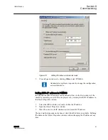
Page 96: ...071162 V1 EN Figure 62 Selecting TCP IP protocol 4 Select Obtain an IP address automatically and Obtain DNS server address automatically Section 8 1MRS756499 A Commissioning 88 RED615 Operation Manual...

Page 97: ...PC with MicroSoft Windows operating system for rear communication 1 To open Network Connections click Start point to Settings click Control Panel and then double click Network Connections 2 Double cli...

Page 98: ...P protocol 4 Choose Use the following IP address Enter an IP address and a subnet mask Make sure that the IP address is unique that is not used by any other IED on the network Section 8 1MRS756499 A C...

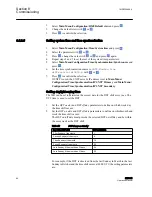
Page 99: ...he wizard by including a new IED in the project or by entering the IED s IP address in the Object Properties window 1 Select the IED to which you want to define the IP address 2 Open the Object Proper...

Page 100: ...re IEC 61850 8 1 and Modbus TCP IP Protocol available for RS 485 RS 232 serial port is Modbus RTU Modbus ASCII To define the settings for the Ethernet port select Main Menu Configuration Communication...

Page 101: ...n and authorized to control the IED After an auxiliary power failure the contrast is restored 8 5 2 3 Changing display symbols To switch between the display symbols IEC 61850 IEC 61617 and IEC ANSI 1...

Page 102: ...SNTP Secondary Setting daylight saving time The IED can be set to determine the correct date for the DST shift every year The UTC time is used to set the DST 1 Set the DST on day and DST off day param...

Page 103: ...er to 0 min 8 5 3 Setting IED parameters 8 5 3 1 Defining setting groups Selecting a setting group for editing 1 Select Main Menu Settings Edit setting group 2 Select the setting group to be edited wi...

Page 104: ...er you see the current setting group and on the right the menu path 5 To browse the parameters scroll the list with and and to select a parameter press The setting group values are indicated with A070...

Page 105: ...The active setting group can be changed by the IED application or manually from the menu 1 Select Main Menu Settings Setting group Active group and press A071150 V3 EN Figure 72 Active setting group 2...

Page 106: ...nputs and press 2 Select the analog input to be configured with or 3 Press change the value with or and press again For CTs the secondary current and primary current need to be set to the correct valu...

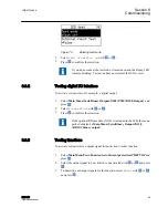
Page 107: ...ss 2 Select False or True with or 3 Press to confirm the selection If the optional BIO module X110 is included in the IED the menu path could also be Main Menu Tests Binary Outputs X110 BIO1 binary ou...

Page 108: ...al fault is tested 1 Select Main Menu Tests IED test Internal fault test and press A071156 V3 EN Figure 75 Internal fault test 2 Select False or True with or 3 Press to confirm the selection 8 7 ABB P...

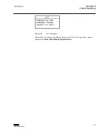
Page 109: ...N Figure 76 LCT indication The number of composition changes can be seen from the Composition changes parameter in Main Menu Monitoring IED status 1MRS756499 A Section 8 Commissioning RED615 101 Opera...

Page 110: ...102...

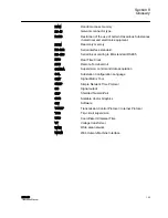
Page 111: ...ng unit CSV Comma separated values CT Current transformer DHCP Dynamic Host Configuration Protocol allows devices joining the network to dynamically receive an IP address from the DHCP server that con...

Page 112: ...k LC Connector type for glass fibre cable LCD Liquid crystal display LCP Liquid crystal polymer LCT Life cycle traceability LED Light emitting diode LHMI Local Human Machine Interface LON Local operat...

Page 113: ...mote Terminal Unit SCADA Supervision control and data acquisition SCL Substation Configuration Language SMT Signal Matrix Tool SNTP Simple Network Time Protocol SO Signal output STP Shielded Twisted P...

Page 114: ...106...

Page 115: ...107...

Page 116: ...1MRS756499 A Copyright 2008 ABB All rights reserved ABB Oy Distribution Automation P O Box 699 FI 65101 VAASA Finland Phone 358 10 22 11 Fax 358 10 22 41094 www abb com substationautomation...

Reviews: