background image


RELION® 650 SERIES

— 

Line differential protection RED650 

Version 2.2 

Technical manual

Summary of Contents for RED650

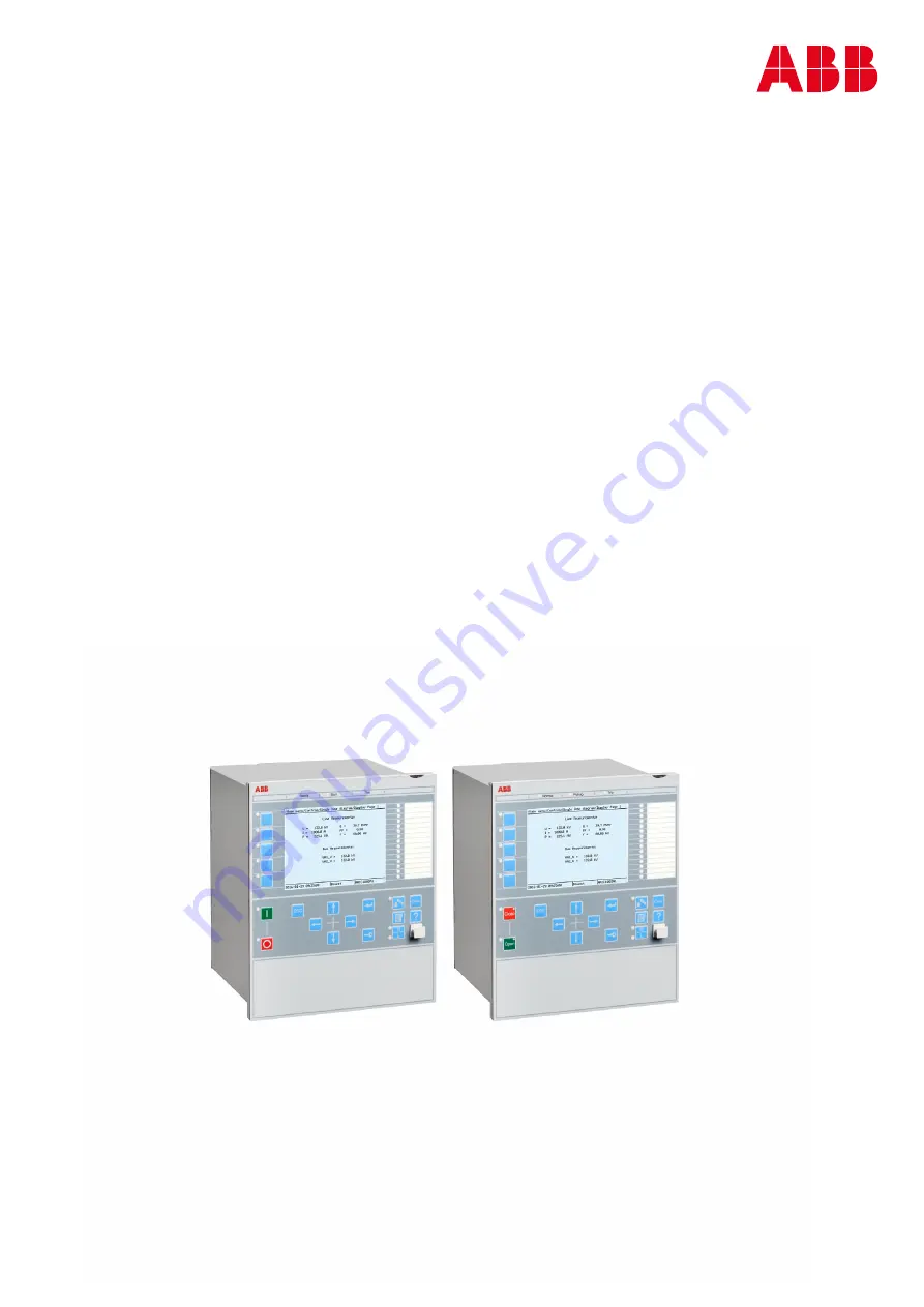
Page 1: ...RELION 650 SERIES Line differential protection RED650 Version 2 2 Technical manual...

Page 2: ......

Page 3: ...Document ID 1MRK 505 394 UEN Issued October 2017 Revision A Product version 2 2 1 Copyright 2017 ABB All rights reserved...

Page 4: ...rms of such license This product includes software developed by the OpenSSL Project for use in the OpenSSL Toolkit http www openssl org This product includes cryptographic software written developed b...

Page 5: ...roduct failure would create a risk for harm to property or persons including but not limited to personal injuries or death shall be the sole responsibility of the person or entity applying the equipme...

Page 6: ...d concerning electrical equipment for use within specified voltage limits Low voltage directive 2006 95 EC This conformity is the result of tests conducted by ABB in accordance with the product standa...

Page 7: ...Control and monitoring functions 42 Communication 45 Basic IED functions 47 Section 3 Analog inputs 49 Introduction 49 Function block 49 Signals 50 Settings 51 Monitored data 56 Operation principle 5...

Page 8: ...keys 83 Functionality 83 Operation principle 83 Section 6 Differential protection 85 Line differential protection 85 Identification 85 Functionality 85 Line differential protection for 3 CT sets 2 3...

Page 9: ...schemes 133 Measurement 140 Technical data 145 Power swing detection ZMRPSB 146 Identification 146 Functionality 146 Function block 146 Signals 146 Settings 147 Operation principle 148 Resistive reach...

Page 10: ...protection EFPIOC 179 Identification 179 Functionality 179 Function block 179 Signals 179 Settings 180 Monitored data 180 Operation principle 180 Technical data 181 Directional residual overcurrent pr...

Page 11: ...RBRF 212 Identification 212 Functionality 212 Function block 213 Signals 213 Settings 214 Monitored data 215 Operation principle 215 Technical data 218 Pole discordance protection CCPDSC 219 Identific...

Page 12: ...cal data 253 Two step residual overvoltage protection ROV2PTOV 254 Identification 254 Functionality 254 Function block 255 Signals 255 Settings 256 Monitored data 257 Operation principle 258 Measureme...

Page 13: ...ctionality 277 Function block 278 Signals 278 Settings 278 Operation principle 279 Measurement principle 279 Time delay 279 Blocking 280 Design 280 Technical data 281 Section 11 Secondary system super...

Page 14: ...ata 320 Autorecloser for 1 phase 2 phase and or 3 phase operation SMBRREC 321 Identification 321 Functionality 321 Function block 322 Signals 322 Settings 324 Operation principle 326 Terminology expla...

Page 15: ...R 371 Functionality 371 Function block 372 Signals 372 Settings 373 Operation principle 373 Proxy for signals from switching device via GOOSE XLNPROXY 378 Functionality 378 Function block 378 Signals...

Page 16: ...Signals 393 Settings 393 Operation principle 394 AutomationBits command function for DNP3 0 AUTOBITS 394 Identification 394 Functionality 394 Function block 395 Signals 395 Settings 396 Operation pri...

Page 17: ...ed logic 412 Technical data 414 Local acceleration logic ZCLCPSCH 414 Identification 414 Functionality 414 Function block 414 Signals 415 Settings 415 Operation principle 416 Zone extension 416 Loss o...

Page 18: ...4 Logic diagram 438 Technical data 440 General start matrix block SMAGAPC 441 Identification 441 Functionality 441 Function block 441 Signals 441 Settings 442 Operation principle 442 Trip matrix logic...

Page 19: ...60 Function block 460 Signals 461 Technical data 461 Controllable gate function block GATE 461 Function block 461 Signals 461 Settings 462 Technical data 462 Inverter function block INV 462 Function b...

Page 20: ...nical data 471 Extension logic package 471 Fixed signals FXDSIGN 471 Identification 471 Functionality 471 Function block 472 Signals 472 Settings 472 Operation principle 472 Boolean 16 to Integer conv...

Page 21: ...al data 485 Elapsed time integrator with limit transgression and overflow supervision TEIGAPC 485 Identification 485 Functionality 485 Function block 486 Signals 486 Settings 487 Operation principle 4...

Page 22: ...age and current sequence measurements VMSQI CMSQI 530 Technical data 530 Gas medium supervision SSIMG 532 Identification 532 Functionality 532 Function block 533 Signals 533 Settings 534 Monitored dat...

Page 23: ...553 Function block 554 Signals 554 Settings 555 Operation principle 557 Disturbance report DRPRDRE 558 Identification 558 Functionality 558 Function block 559 Signals 561 Settings 563 Monitored data...

Page 24: ...principle 599 Design 600 Reporting 601 Function block 601 Signals 601 Settings 602 Monitored data 602 Technical data 603 Running hour meter TEILGAPC 603 Identification 603 Functionality 603 Function b...

Page 25: ...ignals 626 Monitored data 627 Redundant communication 627 Identification 627 Functionality 628 Operation principle 628 Merging unit 630 Introduction 630 Settings 631 Monitored data 631 Routes 636 Intr...

Page 26: ...ication 647 Functionality 647 Function block 647 Signals 647 Settings 648 Operation principle 648 GOOSE function block to receive an integer value GOOSEINTRCV 649 Identification 649 Functionality 649...

Page 27: ...tion 663 Functionality 663 Function block 664 Signals 664 Settings 666 Operation principle 666 IEC UCA 61850 9 2LE communication protocol 666 Introduction 666 Function block 666 Signals 667 Output sig...

Page 28: ...ionality 710 Identification 710 Function block 710 Signals 710 Settings 710 Function status earth fault for IEC 60870 5 103 I103EF 711 Functionality 711 Identification 711 Function block 711 Signals 7...

Page 29: ...ality 721 Identification 721 Function block 722 Signals 722 Settings 722 Function commands user defined for IEC 60870 5 103 I103USRCMD 722 Functionality 722 Identification 723 Function block 723 Signa...

Page 30: ...urity alarm SECALARM 743 Signals 743 Settings 743 Activity logging parameters ACTIVLOG 743 Activity logging ACTIVLOG 743 Settings 744 Section 19 Remote communication 745 Binary signal transfer 745 Ide...

Page 31: ...ith internal event list INTERRSIG 764 Functionality 764 Function block 764 Signals 764 Settings 764 Operation principle 764 Internal signals 766 Supervision of analog inputs 768 Technical data 768 Cha...

Page 32: ...gs 793 Product information PRODINF 794 Functionality 794 Settings 794 Factory defined settings 794 Signal matrix for binary inputs SMBI 795 Functionality 795 Function block 795 Signals 796 Operation p...

Page 33: ...812 Introduction 812 Functionality 812 Technical data 813 Power supply module PSM 813 Introduction 813 Design 814 Technical data 814 Local human machine interface Local HMI 814 Transformer input modul...

Page 34: ...ion 842 Design 842 Technical data 843 IRIG B time synchronization module IRIG B 844 Introduction 844 Design 844 Settings 845 Technical data 845 Dimensions 846 Case with rear cover 846 Case without rea...

Page 35: ...ide by side flush mounting 859 Technical data 859 Enclosure 859 Electrical safety 860 Connection system 860 Influencing factors 861 Type tests according to standard 862 Section 23 Labels 865 Labels on...

Page 36: ...30...

Page 37: ...r functions which measure an analogue signal which do not have corresponding primary quantity the 1 1 ratio shall be set for the used analogue inputs on the IED Example of such functions are HZPDIF RO...

Page 38: ...3 1 Product documentation set GUID 3AA69EA6 F1D8 47C6 A8E6 562F29C67172 v15 IEC07000220 4 en vsd Planning purchase Engineering Installing Commissioning Operation Maintenance Decommissioning Deinstall...

Page 39: ...o identify disturbances and how to view calculated and measured power grid data to determine the cause of a fault The application manual contains application descriptions and setting guidelines sorted...

Page 40: ...N Communication protocol manual DNP3 1MRK 511 413 UUS Communication protocol manual IEC 60870 5 103 1MRK 511 416 UEN Communication protocol manual IEC 61850 Edition 1 1MRK 511 414 UEN Communication pr...

Page 41: ...g related to the concept discussed in the text It might indicate the presence of a hazard which could result in corruption of software or damage to equipment or property The information icon alerts th...

Page 42: ...d to another function block in the application configuration to achieve a valid application configuration Logic diagrams describe the signal logic inside the function block and are bordered by dashed...

Page 43: ...AR GF2PTOV GF2PTUC GF2PTUV GF2PVOC PH1PTRC CVMMXN CVMMXN CVMMXN DPGAPC DPGGIO DPGAPC DRPRDRE DRPRDRE DRPRDRE EF4PTOC EF4LLN0 EF4PTRC EF4RDIR GEN4PHAR PH1PTOC EF4PTRC EF4RDIR GEN4PHAR PH1PTOC EFPIOC EF...

Page 44: ...QCRSV RCHLCCH RCHLCCH RCHLCCH REFPDIF REFPDIF REFPDIF ROV2PTOV GEN2LLN0 PH1PTRC ROV2PTOV PH1PTRC ROV2PTOV SCHLCCH SCHLCCH SCHLCCH SCILO SCILO SCILO SCSWI SCSWI SCSWI SESRSYN RSY1LLN0 AUT1RSYN MAN1RSY...

Page 45: ...0 PH1PTRC UV2PTUV PH1PTRC UV2PTUV VMMXU VMMXU VMMXU VMSQI VMSQI VMSQI VNMMXU VNMMXU VNMMXU VSGAPC VSGGIO VSGAPC WRNCALH WRNCALH WRNCALH ZCLCPSCH ZCLCPLAL ZCLCPSCH ZCPSCH ZCPSCH ZCPSCH ZCRWPSCH ZCRWPSC...

Page 46: ...40...

Page 47: ...ion included in packages A03 refer to ordering details IEC 61850 or function name ANSI Function description Line Differential RED650 A11 Differential protection LT3CPDIF 87LT Line differential protect...

Page 48: ...Voltage protection UV2PTUV 27 Two step undervoltage protection 1 OV2PTOV 59 Two step overvoltage protection 1 ROV2PTOV 59N Two step residual overvoltage protection 1 Frequency protection SAPTUF 81 Und...

Page 49: ...3 50 I103IEDCMD IED commands for IEC 60870 5 103 1 I103USRCMD Function commands user defined for IEC 60870 5 103 4 Secondary system supervision CCSSPVC 87 Current circuit supervison 1 FUFSPVC Fuse fai...

Page 50: ...measurement 6 CMMXU Current measurement 10 VMMXU Voltage measurement phase phase 6 CMSQI Current sequence measurement 6 VMSQI Voltage sequence measurement 6 VNMMXU Voltage measurement phase earth 6 A...

Page 51: ...TEILGAPC Running hour meter 6 Metering PCFCNT Pulse counter logic 16 ETPMMTR Function for energy calculation and demand handling 6 2 4 Communication GUID 5F144B53 B9A7 4173 80CF CD4C84579CB5 v15 IEC...

Page 52: ...03 serial communication for RS485 1 AGSAL Generic security application component 1 LD0LLN0 IEC 61850 LD0 LLN0 1 SYSLLN0 IEC 61850 SYS LLN0 1 LPHD Physical device information 1 PCMACCS IED configuratio...

Page 53: ...reversal and weak end infeed logic for residual overcurrent protection 1 2 5 Basic IED functions GUID C8F0E5D2 E305 4184 9627 F6B5864216CA v12 Table 4 Basic IED functions IEC 61850 or function name D...

Page 54: ...r function name ANSI Description LHMICTRL Local HMI signals LANGUAGE Local human machine language SCREEN Local HMI Local human machine screen behavior FNKEYTY1 FNKEYTY5 FNKEYMD1 FNKEYMD5 Parameter set...

Page 55: ...g channel s phase angle will always be fixed to zero degrees and remaining analog channel s phase angle information will be shown in relation to this analog input During testing and commissioning of t...

Page 56: ...age input 11 CH12 U STRING Analogue voltage input 12 PID 3924 OUTPUTSIGNALS v7 Table 7 TRM_9I_3U Output signals Name Type Description STATUS BOOLEAN Analogue input module status CH1 I STRING Analogue...

Page 57: ...CH5 I STRING Analogue current input 5 CH6 I STRING Analogue current input 6 CH7 I STRING Analogue current input 7 CH8 I STRING Analogue current input 8 CH9 I STRING Analogue current input 9 CH10 I ST...

Page 58: ...MU3 L3U MU3 L4U MU4 L1I L4I MU4 L1U L4U MU5 L1I L4I MU5 L1U L4U MU6 L1I L4I MU7 L1I L4I MU7 L1U L4U MU8 L1I L4I MU8 L1U L4U MU9 L1I L4I MU9 L1U L4U MU10 L1I L4I MU10 L1U L4U MU11 L1I L4I MU11 L1U L4U...

Page 59: ...1 Rated CT secondary current CTprim5 1 99999 A 1 3000 Rated CT primary current CTStarPoint6 FromObject ToObject ToObject ToObject towards protected object FromObject the opposite CTsec6 1 10 A 1 1 Ra...

Page 60: ...5 1 10 A 1 1 Rated CT secondary current CTprim5 1 99999 A 1 3000 Rated CT primary current CTStarPoint6 FromObject ToObject ToObject ToObject towards protected object FromObject the opposite CTsec6 1 1...

Page 61: ...t the opposite CTsec4 1 10 A 1 1 Rated CT secondary current CTprim4 1 99999 A 1 3000 Rated CT primary current CTStarPoint5 FromObject ToObject ToObject ToObject towards protected object FromObject the...

Page 62: ...DDATA v3 Table 13 AISVBAS Monitored data Name Type Values Range Unit Description Status INTEGER 0 Ok 1 Error 2 AngRefLow 3 Uncorrelated Service value status PID 3923 MONITOREDDATA v6 Table 14 TRM_7I_5...

Page 63: ...n for directional functions Measured quantity is positive when flowing towards the object e g P Q I Reverse Forward Definition of direction for directional functions e g P Q I Measured quantity is pos...

Page 64: ...nd 250 Ir one half wave Burden 20 mVA at Ir 1 A 150 mVA at Ir 5 A max 350 A for 1 s when COMBITEST test switch is included Voltage inputs Rated voltage Ur 110 or 220 V Operating range 0 340 V Thermal...

Page 65: ...n the signal goes down to 0 again 4 1 2 Oscillation filter GUID 41B89E6F 50C3 44BF 9171 3CC82EB5CA15 v4 Binary input wiring can be very long in substations and there are electromagnetic fields from fo...

Page 66: ...release limit 4 1 3 2 Setting parameters for binary input output module PID 4050 SETTINGS v2 Table 20 IOMIN Non group settings basic Name Values Range Unit Step Default Description Operation Off On O...

Page 67: ...61850 identification IEC 60617 identification ANSI IEEE C37 2 device number Local HMI signals LHMICTRL 5 2 2 Function block GUID A8AC51E9 5BD7 4A80 9576 4816F14DD08D v2 LHMICTRL CLRLEDS HMI ON RED S...

Page 68: ...nction description IEC 61850 identification IEC 60617 identification ANSI IEEE C37 2 device number Basic part for LED indication module LEDGEN Basic part for LED indication HW module GRP1_LED1 GRP1_LE...

Page 69: ...LED1 Input signals Name Type Default Description HM1L01R BOOLEAN 0 Red indication of LED1 local HMI alarm group 1 HM1L01Y BOOLEAN 0 Yellow indication of LED1 local HMI alarm group 1 HM1L01G BOOLEAN 0...

Page 70: ...module GUID EECAE7FA 7078 472C A429 F7607DB884EB v2 5 4 1 Identification GUID E6611022 5EA3 420D ADCD 9D1E7604EFEB v1 Function description IEC 61850 identification IEC 60617 identification ANSI IEEE C...

Page 71: ...1 LabelOn 0 18 1 LCD_FN1_ON Label for LED on state LabelOff 0 18 1 LCD_FN1_OFF Label for LED off state PID 6452 SETTINGS v2 Table 31 FNKEYTY1 Non group settings basic Name Values Range Unit Step Defau...

Page 72: ...EN US Figure 7 Local human machine interface The LHMI of the IED contains the following elements Keypad Display LCD LED indicators Communication port for PCM600 Section 5 1MRK 505 394 UEN A Local Hum...

Page 73: ...The push buttons are also used to acknowledge alarms reset indications provide help and switch between local and remote control mode The keypad also contains programmable push buttons that can be con...

Page 74: ...avigation and command push buttons and RJ 45 communication port 1 5 Function button 6 Close 7 Open 8 Escape 9 Left 10 Down 11 Up 12 Right 13 Key 14 Enter 15 Remote Local 16 Uplink LED 17 Not in use 18...

Page 75: ...chrome liquid crystal display LCD with a resolution of 320 x 240 pixels The character size can vary The amount of characters and rows fitting the view depends on the character size and the view that i...

Page 76: ...ent The status area shows the current IED time the user that is currently logged in and the object identification string which is settable via the LHMI or with PCM600 If text pictures or other items d...

Page 77: ...The function key button panel shows on request what actions are possible with the function buttons Each function button has a LED indication that can be used as a feedback signal for the function but...

Page 78: ...panel The function button and indication LED panels are not visible at the same time Each panel is shown by pressing one of the function buttons or the Multipage button Pressing the ESC button clears...

Page 79: ...ng that button cycles through the three pages A lit or un acknowledged LED is indicated with a highlight Such lines can be selected by using the Up Down arrow buttons Pressing the Enter key shows deta...

Page 80: ...that presents the healthy status of the IED The yellow and red LEDs are user configured The yellow LED can be used to indicate that a disturbance report is triggered steady or that the IED is in test...

Page 81: ...as elapsed In sequence 6 the restarting or reset mode means that upon occurrence of any new event all previous indications will be reset This facilitates that only the LED indications related to the l...

Page 82: ...owledgement are only working in collecting Coll mode Sequence 5 is working according to Latched type and collecting mode while Sequence 6 is working according to Latched type and re starting Reset mod...

Page 83: ...This sequence is the same as Sequence 1 Follow S but the LEDs are flashing instead of showing steady light Sequence 3 LatchedAck F S SEMOD56072 50 v2 This sequence has a latched function and works in...

Page 84: ...nal RED LED Acknow IEC09000313_1_en vsd Activating signal GREEN R R G IEC09000313 V1 EN US Figure 18 Operating Sequence 3 LatchedAck F S 2 colors involved GUID A652A49D F016 472D 8D38 6D3E75DAB1DB v3...

Page 85: ...vation of the input signal the indication will light up with a steady light The difference to sequence 3 and 4 is that indications that are still activated will not be affected by the reset that is im...

Page 86: ...Also in this case indications that are still activated will not be affected by manual reset that is immediately after the positive edge of that the manual reset has been executed a new reading and sto...

Page 87: ...ows the timing diagram for a new indication after tRestart time has elapsed IEC01000240_2_en vsd Activating signal 2 LED 2 Manual reset Activating signal 1 Automatic reset LED 1 Disturbance tRestart D...

Page 88: ...equence 6 LatchedReset S two indications within same disturbance but with reset of activating signal between Figure 26 shows the timing diagram for manual reset IEC01000242_2_en vsd Activating signal...

Page 89: ...utputs can in turn be used to control other function blocks for example switch control blocks binary I O outputs etc FNKEYMD1 FNKEYMD5 function block also has a number of settings and parameters that...

Page 90: ...500ms pulse time pulse time pulse time 500ms IEC09000332_2_en vsd Input value Output value IEC09000332 V2 EN US Figure 29 Sequence diagram for setting PULSED Input function GUID 8EA4AE21 7A74 403A 84...

Page 91: ...on zone In such application the differential protection is based on the ampere turns balance between the transformer windings Three winding transformers are correctly represented with vector group com...

Page 92: ...ter Slave condition for the differential function appears automatically when the setting Operation for the differential function is set to Off For line differential protection we recommend that all fe...

Page 93: ...HL3 ALARM OPENCT OPENCTAL IDL1 IDL2 IDL3 IDL1MAG IDL2MAG IDL3MAG IBIAS IDNSMAG IEC06000254 V3 EN US Figure 31 LT3CPDIF function block M12591 3 v4 LDLPSCH CTFAIL OUTSERV BLOCK TRIP TRL1 TRL2 TRL3 TRLOC...

Page 94: ...art signal from phase L2 STL3 BOOLEAN Start signal from phase L3 INTFAULT BOOLEAN Internal fault has been detected EXTFAULT BOOLEAN External fault has been detected BLK2H BOOLEAN Common block signal d...

Page 95: ...terminal is out of service BLOCK BOOLEAN 0 Block of function PID 3560 OUTPUTSIGNALS v7 Table 35 LDLPSCH Output signals Name Type Description TRIP BOOLEAN General trip from differential protection syst...

Page 96: ...ue of neg seq curr as multiple of IBase CrossBlockEn No Yes No Off On selection of the cross block logic ChargCurEnable Off On Off Off On selection for compensation of charging currents AddDelay Off O...

Page 97: ...harm dif curr in p 0 01 1000 00 0 01 0 02 Settable curve parameter user programmable curve type a 0 01 1000 00 0 01 0 14 Settable curve parameter user programmable curve type b 0 01 1000 00 0 01 1 00...

Page 98: ...t channel X RatVoltW1TraB 1 0 9999 9 kV 0 1 130 0 Transformer B rated voltage kV on winding 1 HV winding RatVoltW2TraB 1 0 9999 9 kV 0 1 130 0 Transformer B rated voltage kV on winding 2 LV winding Cl...

Page 99: ...3 IDNSMAG REAL A Magnitude of the negative sequence differential current NSANGLE REAL deg Angle between local and remote neg seq currents ICHARGE REAL A Amount of compensated charging current 6 1 7 Op...

Page 100: ...L1SM CH1IL2SM CH1IL3SM CH2IL1SM Curr samples from all ends CH1IL1RE CH1IL1IM CH1IL2RE CH1IL2IM Currents from all ends as phasors CH1INSRE CH1INSIM CH1INSRE CH1INSIM Neg seq currents from all ends as p...

Page 101: ...ent on the other hand is considered the greatest phase current in any line end and it is common for all the tree phases The two slopes SlopeSection1 SlopeSection2 and breakpoints EndSection1 EndSectio...

Page 102: ...characteristics where 100 Ioperate slope Irestrain D D EQUATION1246 V1 EN US and where the restrained characteristic is defined by the settings 1 IdMin 2 EndSection1 3 EndSection2 4 SlopeSection2 5 Sl...

Page 103: ...hown in Figure 35 where the directional characteristic is defined by the two setting parameters IminNegSeq and NegSeqRoa 0 deg 180 deg 90 deg 270 deg 120 deg IMinNegSeq If one or the other of currents...

Page 104: ...internal by the negative sequence fault discriminator a trip command is issued under the condition that at least one start signal has been issued while all eventual block signals issued by the harmon...

Page 105: ...US Figure 36 Simplified block diagram Remembering that current values plotted above the characteristic formed by IdMin and the dual slope in Figure 35 are said to give a start the output logic can be...

Page 106: ...d 5th harmonic analysis is only activated temporarily under external fault conditions or when the bias current is lower than 1 25 IBase Classification of a fault as external by the negative sequence f...

Page 107: ...itude error of approximately 31 The corresponding figures for a 60 Hz system are 4 and 38 respectively In Line differential protection the time coordination is made with the so called echo method Each...

Page 108: ...nd current In one and a half breaker arrangements there are two local currents meaning two 64 kbit s channels to each remote substation Alternatively it is possible to add together the two local curre...

Page 109: ...communication exchange is made only once every 5 ms This means that at in each telegram sent 5 consecutive current samples in a 50 Hz system and 6 consecutive current samples in a 60 Hz system three...

Page 110: ...CT circuit may cause an unexpected and unwanted operation of the Line differential protection under normal load conditions Damage of secondary equipment may occur due to high voltage from open CT circ...

Page 111: ...open CT starts 60 seconds 50 seconds in 60 Hz systems after the bias current has entered the 10 120 range The Open CT detection feature can also be explicitly deactivated by setting OpenCTEnable 0 Of...

Page 112: ...onditions are fulfilled for a longer time than defined by the setting parameter tOCTResetDelay If an open CT has been detected in a separate group of three CTs the algorithm is reset either when the m...

Page 113: ...oteTerm4 TestModeRemoteTerm2 BlockRemoteTerm1 BlockRemoteTerm2 BlockRemoteTerm3 BlockRemoteTerm4 OPEN CT BLK TestModeInput TERMINALOUTOFSERVICE BLOCK LocalDiffBlock LOCALDIFFBLOCKED CTFailOCTToRemote...

Page 114: ...TripL3ToRemote TRIPREMOTE IEC13000260 2 en vsd IEC13000260 V2 EN US Figure 41 Trip signal logic of LDLPSCH Some of the signals in the above block diagrams are used as the internal signals by LDLPSCH T...

Page 115: ...gnal from LDCM Trip from remote terminal 1 in phase L3 tripL3RemoteTerm2 Signal from LDCM Trip from remote terminal 2 in phase L3 tripL1ToRemote Signal to LDCM Trip to remote terminals phase L1 tripL2...

Page 116: ...nction at 10 x IdMin to 0 Min 5 ms Max 15 ms Operate time unrestrained function at 0 to 10 x IdUnre Min 5 ms Max 15 ms Reset time unrestrained function at 10 x IdUnre to 0 Min 15 ms Max 30 ms Operate...

Page 117: ...al mode Zone1 and zone2 are designed to measure in forward direction only while one zone ZRV is designed to measure in the reverse direction This makes them suitable together with a communication sche...

Page 118: ...2 BLKTRZ3 BLKTRZ4 BLKTRZ5 BLKTRZRV EXTNST RELCNDZ1 RELCNDZ2 RELCNDZ3 RELCNDZ4 RELCNDZ5 RELCNDZRV TRIP TRZ1 TRL1Z1 TRL2Z1 TRL3Z1 TRZ2 TRL1Z2 TRL2Z2 TRL3Z2 TRZ3 TRZ4 TRZ5 TRZRV START STZ1 STNDZ1 STZ2 ST...

Page 119: ...ocks and resets zone 4 timers and trip outputs BLKTRZ5 BOOLEAN 0 Blocks and resets zone 5 timers and trip outputs BLKTRZRV BOOLEAN 0 Blocks and resets reverse zone timers and trip outputs EXTNST BOOLE...

Page 120: ...tion STL1Z2 BOOLEAN Start in phase L1 from zone 2 forward direction STL2Z2 BOOLEAN Start in phase L2 from zone 2 forward direction STL3Z2 BOOLEAN Start in phase L3 from zone 2 forward direction STNDZ2...

Page 121: ...erse direction STRVPE BOOLEAN Fault with earth connection detected reverse direction STFW1PH BOOLEAN Single phase fault detected forward direction STFW2PH BOOLEAN Two phase fault detected forward dire...

Page 122: ...on Direction in phase L1 L2Dir INTEGER 1 Forward 2 Reverse 0 No direction Direction in phase L2 L3Dir INTEGER 1 Forward 2 Reverse 0 No direction Direction in phase L3 L1L2Dir INTEGER 1 Forward 2 Rever...

Page 123: ...EAL Ohm ZL12 Amplitude magnitude of instantaneous value ZL12ANGIM REAL deg ZL12 Angle magnitude of instantaneous value ZL23IMAG REAL Ohm ZL23 Amplitude magnitude of instantaneous value ZL23ANGIM REAL...

Page 124: ...e to phase faults for forward and reverse faults are executed in parallel Figure 43 presents an outline of the different measuring loops for the six distance zones IEC05000458 2 en vsd L1 N L2 N L3 N...

Page 125: ...55104B2C9B4 v5 The operation of the phase selection element is primarily based on current change criteria i e delta quantities with significantly increased dependability To handle this there is also a...

Page 126: ...irectional decision The basis is provided by comparing a positive sequence based polarizing voltage with phase currents For extra security especially in making a very fast decision this method is comp...

Page 127: ...in time Namely an intentional time delay will be introduced if no current magnitude change greater than 5 of IBase has been detected for any of the three phase currents 7 1 7 6 Power swings GUID 4DFE...

Page 128: ...hm phase Ohm phase IEC11000416 2 en vsdx 2 2 2 2 2 2 IEC11000416 V2 EN US Figure 44 ZMFPDIS Characteristic for phase to phase measuring ohm loop domain Section 7 1MRK 505 394 UEN A Impedance protectio...

Page 129: ...intention with this illustration is to make clear how the fault resistive reach should be interpreted and set Note in particular that the setting RFPPZx always represents the total fault resistance of...

Page 130: ...haracteristic GUID 9269239B 3A04 44CD BE00 FD850D42836B v2 ZMFPDIS implements quadrilateral and mho characteristic in all the six zones separately Set OpModePEZx or OpModePPZx setting to Mho or Offset...

Page 131: ...with high loading and mild power swing conditions Basic operation characteristics GUID E6CC3CA7 72BE 40FC A557 7BDB62F7BC1E v2 In ZMFPDIS each zone measurement loop characteristic can be set to mho c...

Page 132: ...ZMFPDIS function has only one set of reach setting so the reverse will be the same as for the forward reach meaning that the non directional offset mho characteristic will always be centered around th...

Page 133: ...ne direction For Zone 1 Z R PPZ j X PPZ set 1 1 1 1 1 IECEQUATION15011 V1 EN US Equation 7 where R1PPZ1 is the positive sequence resistive reach for phase to phase fault for zone 1 X1PPZ1 is the posit...

Page 134: ...radius where Z set 1 is settable through the resistance and reactance settings The condition for operation at phase to phase fault is that the angle between the two compensated voltages is greater tha...

Page 135: ...283 v2 GUID DB8CF641 0D3F 4F7A A628 829F3DB0AC5B v1 The measuring of earth faults uses earth return compensation applied in a conventional way The compensation voltage is derived by considering the i...

Page 136: ...lt for zone 1 R0Zx is the zero sequence resistive reach of the line in phase for zone x x 2 5 or RV X0Zx is the zero sequence reactance reach of the line in phase for zone x x 2 5 or RV For an earth f...

Page 137: ...86 4C7B BCEA 3034482BA240 v2 The condition for operation of offset mho at phase to earth fault is that the angle between the two compensated voltages is equal to or greater than 90 see figure 52 The a...

Page 138: ...n an external fault is cleared and high emergency load is transferred onto the protected line The effect of load encroachment is illustrated on the left in figure 53 A load impedance within the charac...

Page 139: ...nt is not a major problem R Z1 ArgLd RLdFw IEC09000248 3 en vsdx X RLdRv 1 IEC09000248 V3 EN US Figure 53 Load encroachment phenomena and shaped load encroachment characteristic 1 7 1 7 9 Simplified l...

Page 140: ...f UBase sqrt 3 instead DirModeZ3 5 Forward Reverse TRUE 1 FW Ln LmLn RV Ln LmLn FW Ln LmLn FW Ln LmLn RV Ln LmLn IEC12000137 2 en vsd IEC12000137 V3 EN US Figure 54 Connection of directional signals t...

Page 141: ...AND DIRL3Zx DIRL1L2Zx DIRL2L3Zx DIRL3L1Zx L1Zx PEZx L2Zx PPZx OR OR OR AND AND AND AND AND AND Integer to Bool L1N L2N L3N L1L2 L2L3 L1L3 RELCNDZx IEC12000140 2 en vsdx L3Zx IEC12000140 V2 EN US Figu...

Page 142: ...nkStart Phase Selection 1st starting zone VTSZ BLKZx BLKTRZx OR OR OR OR OR AND AND OR AND AND AND TimerModeZx Enable PhPh or Ph E PhPh AND AND EXTNST External start IEC12000139 4 en vsdx IEC12000139...

Page 143: ...x STL3Zx AND AND AND TZx BLOCK VTSZ BLKZx t 15 ms AND t 15 ms AND STNDZx OR OR L1Zx L2Zx PPZx NDZx OR PEZx IEC12000138 2 en vsd IEC12000138 V2 EN US Figure 57 Start and trip outputs 1MRK 505 394 UEN A...

Page 144: ...15 ms AND STARTND OR OR t 15 ms AND STPHS t 15 ms AND STPP STPE IEC12000133 2 en vsd IEC12000133 V2 EN US Figure 58 Additional start outputs 1 Section 7 1MRK 505 394 UEN A Impedance protection 138 Li...

Page 145: ...EC12000134 V2 EN US Figure 59 Additional start outputs 2 PHSL1 PHSL1L2 PHSL2L3 STRVL2 STRVL3 RVL1 RVL2 RVL1L2 RVL3 RVL2L3 RVL3L1 BLOCK VTSZ OR t 15 ms AND AND AND AND AND AND AND OR OR OR OR IN presen...

Page 146: ...settings Zero point clamping GUID 4894EF16 3376 48EB 863F 9CE14487ACAB v1 Measured value below zero point clamping limit is forced to zero This allows the noise in the input signal to be ignored The z...

Page 147: ...hysteresis is common for all operating values within one channel Actual value of the measured quantity SEMOD54417 150 v4 The actual value of the measured quantity is available locally and remotely The...

Page 148: ...OD54417 163 v6 If a measuring value is changed compared to the last reported value and the change is larger than the Y pre defined limits that are set by user XDbRepInt then the measuring channel repo...

Page 149: ...the process is not continuous but the values are evaluated with a time interval of one execution cycle from each other The last value reported Y1 in figure 64 serves as a basic value for further measu...

Page 150: ...1850 Phase to earth impedance measurement is calculated based on UL1 IL1 UL2 IL2 UL3 IL3 and phase to phase impedance is calculated based on 1 2 1 2 L L L L U U I I 2 3 2 3 L L L L U U I I 3 1 3 1 L L...

Page 151: ...stance reach Ph E and Ph Ph 0 01 9000 00 ohm l Dynamic overreach 5 at 85 degrees measured with CVTs and 0 5 SIR 30 IEC 60255 121 Reset ratio 105 typically Directional blinders Forward 15 120 degrees R...

Page 152: ...rrence of earth fault currents during a power swing inhibits the ZMRPSB function to allow fault clearance 7 2 3 Function block M13884 3 v5 IEC06000264 2 en vsd ZMRPSB I3P U3P BLOCK BLKI01 BLKI02 BLK1P...

Page 153: ...impedance within inner impedance boundary 7 2 5 Settings PID 3663 SETTINGS v6 Table 51 ZMRPSB Group settings basic Name Values Range Unit Step Default Description Operation Off On Off Operation Mode O...

Page 154: ...ibit at very slow swing Table 53 ZMRPSB Non group settings basic Name Values Range Unit Step Default Description GlobalBaseSel 1 12 1 1 Selection of one of the Global Base Value groups 7 2 6 Operation...

Page 155: ...each corresponding phase L1 L2 and L3 Rset Re n n I U L L EQUATION1183 V2 EN US Equation 13 Im n n Xset I U L L EQUATION1184 V2 EN US Equation 14 The Rset and Xset are R and X boundaries 7 2 6 1 Resis...

Page 156: ...ourth quadrant and for X direction in first and second quadrant 7 2 6 2 Resistive reach in reverse direction M13877 15 v3 To avoid load encroachment in reverse direction the resistive reach is limited...

Page 157: ...magnitude of the current is above the setting of the min operating current IMinOpPE ZMRPSB function can operate in two operating modes The 1 out of 3 operating mode is based on detection of power swi...

Page 158: ...ZOUTL1 loop ZOUTL2 ZOUTL3 OR detected OR loop 0 tP1 0 0 tP2 0 0 0 tW IEC05000113 V2 EN US Figure 67 Detection of power swing in phase L1 IEC01000057 2 en vsd DET L1 DET L2 DET L3 DET1of3 int DET2of3 i...

Page 159: ...SB The internal signals DET1of3 and DET2of3 relate to the detailed logic diagrams in figure 67 and figure 68 respectively Selection of the operating mode is possible by the proper configuration of the...

Page 160: ...l three phases This function prevents the operation of ZMRPSB function in cases when the circuit breaker closes onto persistent single phase fault after single phase autoreclosing dead time if the ini...

Page 161: ...F duration after the enabling signal is reset The protection function can be enabled for tripping during the activated time by connecting the functions included in the terminal to the ZACC input There...

Page 162: ...000 60 000 s 0 001 0 020 Time delay for UI detection s tSOTF 0 000 60 000 s 0 001 1 000 Drop off delay time of switch onto fault function tDLD 0 000 60 000 s 0 001 0 200 Delay time for activation of...

Page 163: ...to Current If all three phase voltages are below the setting UPh and the AutoInitMode setting is set to Voltage If all three phase currents and voltages are below the settings IPh and UPh and the Auto...

Page 164: ...er Range or value Accuracy Operate voltage detection of dead line 1 100 of UBase 0 5 of Ur Operate current detection of dead line 1 100 of IBase 1 0 of Ir Time delay to operate for the switch onto fau...

Page 165: ...sient overreach and short tripping time to allow use as a high set short circuit protection function 8 1 3 Function block M12602 3 v6 IEC04000391 2 en vsd PHPIOC I3P BLOCK ENMULT TRIP TRL1 TRL2 TRL3 I...

Page 166: ...fault Description IP Min 5 2500 IB 1 5 Minimum used operate phase current level in of IBase if IP is less than IP Min then IP is set to IP Min IP Max 5 2500 IB 1 2500 Maximum used operate phase curren...

Page 167: ...s must be activated for trip There is also a possibility to activate a preset change of the set operation current StValMult via a binary input ENMULT In some applications the operation value needs to...

Page 168: ...Iset Dynamic overreach 5 at t 100 ms 8 2 Directional phase overcurrent protection four steps OC4PTOC SEMOD129998 1 v8 8 2 1 Identification M14885 1 v6 Function description IEC 61850 identification IE...

Page 169: ...C I3P U3P BLOCK BLKTR BLKST1 BLKST2 BLKST3 BLKST4 ENMULT1 ENMULT2 ENMULT3 ENMULT4 TRIP TR1 TR2 TR3 TR4 TRL1 TRL2 TRL3 TR1L1 TR1L2 TR1L3 TR2L1 TR2L2 TR2L3 TR3L1 TR3L2 TR3L3 TR4L1 TR4L2 TR4L3 START ST1...

Page 170: ...PID 6973 OUTPUTSIGNALS v3 Table 69 OC4PTOC Output signals Name Type Description TRIP BOOLEAN Trip TR1 BOOLEAN Common trip signal from step1 TR2 BOOLEAN Common trip signal from step2 TR3 BOOLEAN Common...

Page 171: ...2 phase L2 ST2L3 BOOLEAN Start signal from step2 phase L3 ST3L1 BOOLEAN Start signal from step3 phase L1 ST3L2 BOOLEAN Start signal from step3 phase L2 ST3L3 BOOLEAN Start signal from step3 phase L3 S...

Page 172: ...rve type for step 1 I1 5 2500 IB 1 1000 Operating phase current level for step 1 in of IBase t1 0 000 60 000 s 0 001 0 000 Def time delay or add time delay for inverse char of step 1 k1 0 05 999 00 0...

Page 173: ...000 60 000 s 0 001 0 000 Minimum operate time for inverse curves for step 2 I2Mult 1 0 10 0 0 1 2 0 Multiplier for current operate level for step 2 DirMode3 Off Non directional Forward Reverse Non dir...

Page 174: ...rating phase current level for step 4 in of IBase t4 0 000 60 000 s 0 001 2 000 Def time delay or add time delay for inverse char of step 4 k4 0 05 999 00 0 01 0 05 Time multiplier for the inverse tim...

Page 175: ...harmonic restrain I2 Min 5 2500 IB 1 5 Minimum used operating phase current level for step 2 in of IBase if I2 is less than I2 Min then I2 is set to I2 Min I2 Max 5 2500 IB 1 2500 Maximum used operati...

Page 176: ...for step 3 tTRCrv3 0 005 100 000 0 001 13 500 Parameter TR for customer programmable curve for step 3 tCRCrv3 0 1 10 0 0 1 1 0 Parameter CR for customer programmable curve for step 3 HarmBlock3 Off On...

Page 177: ...6973 MONITOREDDATA v3 Table 73 OC4PTOC Monitored data Name Type Values Range Unit Description DIRL1 INTEGER 1 Forward 2 Reverse 0 No direction Direction for phase1 DIRL2 INTEGER 1 Forward 2 Reverse 0...

Page 178: ...tion These settings can be chosen 1 out of 3 2 out of 3 or 3 out of 3 Using a parameter setting MeasType within the general settings for the function OC4PTOC it is possible to select the type of the m...

Page 179: ...ional The direction of a fault is given as the current angle in relation to the voltage angle The fault current and fault voltage for the directional function are dependent on the fault type The selec...

Page 180: ...nt 7 of the set terminal rated current IBase the condition seals in If the fault has caused tripping the trip endures If the fault was detected in the reverse direction the measuring element in the re...

Page 181: ...ps The time characteristic for each step can be chosen as definite time delay or an inverse time delay characteristic A wide range of standardized inverse time delay characteristics is available It is...

Page 182: ...tching state The operation current value Ix is limited to be between Ix Max and Ix Min The default values of the limits are the same as the setting limits for Ix and the limits can only be used for re...

Page 183: ...n be blocked from the binary input BLOCK The binary input BLKSTx x 1 2 3 or 4 blocks the operation of the respective step The start signals from the function can be blocked by the binary input BLKST T...

Page 184: ...harmonic blocking 5 100 of fundamental 2 0 of Ir Independent time delay at 0 to 2 x Iset step 1 4 0 000 60 000 s 0 2 or 35 ms whichever is greater Minimum operate time for inverse curves step 1 4 0 00...

Page 185: ...rcent of the line at minimum source impedance EFPIOC is configured to measure the residual current from the three phase current inputs and can be configured to measure the current from a separate curr...

Page 186: ...in of IBase if IN is greater than IN Max then IN is set to IN Max StValMult 0 5 5 0 0 1 1 0 Multiplier for operate current level Table 80 EFPIOC Non group settings basic Name Values Range Unit Step D...

Page 187: ...king it possible to ensure that the operation value used is reasonable If IN is set outside IN Max and IN Min the closest of the limits to IN is used by the function If IN Max is smaller then IN Min t...

Page 188: ...s It can also be used to provide a system back up for example in the case of the primary protection being out of service due to communication or voltage transformer circuit failure EF4PTOC has an inve...

Page 189: ...nt U3P GROUP SIGNAL Group connection for polarizing voltage I3PPOL GROUP SIGNAL Group connection for polarizing current I3PDIR GROUP SIGNAL Group connection for directional current BLOCK BOOLEAN 0 Gen...

Page 190: ...step 2 STIN3 BOOLEAN Start signal step 3 STIN4 BOOLEAN Start signal step 4 STSOTF BOOLEAN Start signal from earth fault switch onto fault function STFW BOOLEAN Start signal forward direction STRV BOO...

Page 191: ...SOTF UnderTime Off SOTF operation mode Off SOTF Undertime SOTF Undertime ActivationSOTF Open Closed CloseCommand Open Select signal to activate SOTF CB Open Closed Close cmd StepForSOTF Step 2 Step 3...

Page 192: ...IBase t1Min 0 000 60 000 s 0 001 0 000 Minimum operate time for inverse time characteristic step 1 IN1Mult 1 0 10 0 0 1 2 0 Multiplier for the residual current setting value for step 1 HarmBlock1 Off...

Page 193: ...EC Very inv IEC inv IEC Ext inv IEC S T inv IEC L T inv IEC Def Time Reserved Programmable RI type RD type ANSI Def Time Time delay characteristic for step 3 IN3 1 2500 IB 1 33 Residual current operat...

Page 194: ...r the residual current setting value for step 4 HarmBlock4 Off On On Enable block of step 4 from harmonic restrain Table 86 EF4PTOC Group settings advanced Name Values Range Unit Step Default Descript...

Page 195: ...step 2 tACrv2 0 005 200 000 0 001 13 500 Param A for customized inverse trip time curve for step 2 tBCrv2 0 00 20 00 0 01 0 00 Param B for customized inverse trip time curve for step 2 tCCrv2 0 1 10 0...

Page 196: ...0 000 60 000 s 0 001 0 020 Reset time delay for step 4 tPCrv4 0 005 3 000 0 001 1 000 Param P for customized inverse trip time curve for step 4 tACrv4 0 005 200 000 0 001 13 500 Param A for customized...

Page 197: ...input used for the current polarizing quantity Provides polarizing current to the directional functionality This current is normally taken from the grounding of a power transformer 4 I3PDIR input used...

Page 198: ...2 IL3 0 EQUATION1874 V2 EN US Equation 23 where IL1 IL2 and IL3 are fundamental frequency phasors of three individual phase currents The residual current is pre processed by a discrete Fourier filter...

Page 199: ...the residual voltage is derived This phasor is used together with the phasor of the operating directional current in order to determine the direction to the earth fault Forward Reverse In order to en...

Page 200: ...in order to calculate the equivalent polarizing voltage UIPol in accordance with the following formula 0s UIPol Z IPol RNPol j XNPol IPol EQUATION1877 V2 EN US Equation 28 which will be then used tog...

Page 201: ...n the protection M13941 152 v6 The base quantities are entered as global settings for all functions in the IED Base current IBase shall be entered as rated phase current of the protected object in pri...

Page 202: ...o prevent operation of the step if the second harmonic content in the residual current exceeds the preset level Multiplier for scaling of the set residual current pickup value by external binary signa...

Page 203: ...input BLKTR 8 4 7 8 Directional supervision element with integrated directional comparison function M13941 179 v11 At least one of the four residual overcurrent steps shall be set as directional in or...

Page 204: ...onal supervision element are The directional element will be internally enabled to operate as soon as Iop is bigger than 40 of IN Dir and the directional condition is fulfilled in the set direction Th...

Page 205: ...mber a a b b T F 0 0 polMethod Current OR IEC07000067 V6 EN US Figure 87 Simplified logic diagram for directional supervision element with integrated directional comparison step 8 4 7 9 Second harmoni...

Page 206: ...delayed compared to the first transformer Therefore we have high 2nd harmonic current component initially After a short period this current is however small and the normal 2nd harmonic blocking resets...

Page 207: ...set to activate SOTF the under time logic or both When the circuit breaker is closing there is a risk to close it onto a permanent fault for example during an autoreclosing sequence The SOTF logic wi...

Page 208: ...after switching of the circuit breaker The under time logic is activated either from change in circuit breaker position or from circuit breaker close and open command pulses This selection is done by...

Page 209: ...cal data IP11455 1 v1 M15223 1 v17 Table 89 EF4PTOC technical data Function Range or value Accuracy Operate current step 1 4 1 2500 of IBase 1 0 of Ir at I Ir 1 0 of I at I Ir Reset ratio 95 at 10 250...

Page 210: ...to 10 x Iset Min 5 ms Max 20 ms Reset time start non directional at 10 x Iset to 0 Min 20 ms Max 35 ms Critical impulse time 10 ms typically at 0 to 2 x Iset Impulse margin time 15 ms typically 8 5 Th...

Page 211: ...5 3 Function block M12627 3 v8 LCPTTR I3P BLOCK BLKTR ENMULT AMBTEMP SENSFLT RESET TRIP START ALARM LOCKOUT IEC13000199 1 en vsd IEC13000199 V1 EN US LFPTTR I3P BLOCK BLKTR ENMULT AMBTEMP SENSFLT RESE...

Page 212: ...LARM BOOLEAN Alarm signal LOCKOUT BOOLEAN Lockout signal PID 3909 OUTPUTSIGNALS v8 Table 93 LFPTTR Output signals Name Type Description TRIP BOOLEAN Trip START BOOLEAN Start Signal ALARM BOOLEAN Alarm...

Page 213: ...gs basic Name Values Range Unit Step Default Description Operation Off On Off Operation Off On TRef 0 600 Deg F 1 160 End temperature rise above ambient of the line when loaded with IRef IRef 0 400 IB...

Page 214: ...me to trip in min TENRECL REAL Estimated time to reset of lockout in min TEMP REAL Temperature Fahrenheit Calculated temperature of the device TEMPAMB REAL Temperature Fahrenheit Ambient temperature u...

Page 215: ...e actual temperature and t is the set thermal time constant for the protected device line or cable The actual temperature of the protected component line or cable is calculated by adding the ambient t...

Page 216: ...ambient temperature The calculated time to reset of lockout is available as a real figure signal TENRECL This signal is enabled when the LOCKOUT output is activated In some applications the measured...

Page 217: ...of time to reset of lockout Calculation of actual temperature Lockout logic AMBTEMP START TEMP TRIP LOCKOUT TTRIP TENRECL I3P ENMULT SENSFLT ALARM BLKTR BLOCK IEC09000637 2 en vsd IEC09000637 V2 EN US...

Page 218: ...perature 0 200 C 0 400 F 2 0 C 4 0 F Operate temperature 0 300 C 0 600 F 2 0 C 4 0 F Reset level temperature 0 300 C 0 600 F 2 0 C 4 0 F 8 6 Breaker failure protection CCRBRF IP14514 1 v6 8 6 1 Identi...

Page 219: ...6 3 Function block M11944 3 v7 IEC06000188 2 en vsd CCRBRF I3P BLOCK START STL1 STL2 STL3 CBCLDL1 CBCLDL2 CBCLDL3 CBFLT TRBU TRBU2 TRRET TRRETL1 TRRETL2 TRRETL3 CBALARM IEC06000188 V2 EN US Figure 93...

Page 220: ...n Operation Off On Off Operation Off On FunctionMode Current Contact Current Contact Current Detection for trip based on Current Contact Current Contact BuTripMode 2 out of 4 1 out of 3 1 out of 4 1 o...

Page 221: ...iple M16914 3 v9 Breaker failure protection CCRBRF is initiated from the protection trip command either from protection functions within the IED or from external protection devices The start signal ca...

Page 222: ...p pulse and the back up trip pulse 2 are settable The re trip pulse the back up trip pulse and the back up trip pulse 2 will however sustain as long as there is an indication of closed breaker In the...

Page 223: ...977 2 en vsd FunctionMode OR OR Current Contact Current and Contact 1 IP CB Closed L1 IL1 IEC09000977 V2 EN US Figure 95 Simplified logic scheme of the CCRBRF CB position evaluation t t1 tPulse AND AN...

Page 224: ...h L2 Current High L3 have logical value 1 when the current in the respective phase has the magnitude larger than the setting parameter IP 8 6 8 Technical data IP10269 1 v1 M12353 1 v13 Table 108 CCRBR...

Page 225: ...ification IEC 60617 identification ANSI IEEE C37 2 device number Pole discordance protection CCPDSC PD SYMBOL S V1 EN US 52PD 8 7 2 Functionality M13269 3 v15 An open phase can cause negative and zero...

Page 226: ...o CB OPENCMD BOOLEAN 0 Open order to CB EXTPDIND BOOLEAN 0 Pole discordance signal from CB logic POLE1OPN BOOLEAN 1 Pole one opened indication from CB POLE1CL BOOLEAN 0 Pole one closed indication from...

Page 227: ...n of IBase Table 112 CCPDSC Non group settings basic Name Values Range Unit Step Default Description GlobalBaseSel 1 12 1 1 Selection of one of the Global Base Value groups 8 7 6 Monitored data PID 35...

Page 228: ...s case the logic is realized within the function If the inputs are indicating pole discordance the trip timer is started This timer will give a trip signal after the set delay Pole discordance can als...

Page 229: ...based CCPDSC is blocked if The IED is in TEST mode and CCPDSC has been blocked from the local HMI The input signal BLOCK is high The input signal BLKDBYAR is high The BLOCK signal is a general purpos...

Page 230: ...highest current in the three phases the highest phase current is greater than CurrRelLevel of IBase If these conditions are true an unsymmetrical condition is detected and the internal signal INPS is...

Page 231: ...r value Accuracy Operate current 0 100 of IBase 1 0 of Ir Independent time delay between trip condition and trip signal 0 000 60 000 s 0 2 or 30 ms whichever is greater 1MRK 505 394 UEN A Section 8 Cu...

Page 232: ...226...

Page 233: ...oltages can occur in the power system during faults or abnormal conditions The two step undervoltage protection function UV2PTUV can be used to open circuit breakers to prepare for system restoration...

Page 234: ...ck of step 1 BLKTR2 BOOLEAN 0 Block of operate signal step 2 BLKST2 BOOLEAN 0 Block of step 2 PID 3586 OUTPUTSIGNALS v7 Table 116 UV2PTUV Output signals Name Type Description TRIP BOOLEAN Trip TR1 BOO...

Page 235: ...rve type for step 1 OpMode1 1 out of 3 2 out of 3 3 out of 3 1 out of 3 Number of phases required for op 1 of 3 2 of 3 3 of 3 from step 1 U1 1 0 100 0 UB 0 1 70 0 Voltage setting start val DT IDMT in...

Page 236: ...ues Range Unit Step Default Description tReset1 0 000 60 000 s 0 001 0 025 Reset time delay used in IEC Definite Time curve step 1 ResetTypeCrv1 Instantaneous Frozen timer Linearly decreased Instantan...

Page 237: ...586 MONITOREDDATA v6 Table 120 UV2PTUV Monitored data Name Type Values Range Unit Description UL1 REAL kV Voltage in phase L1 UL2 REAL kV Voltage in phase L2 UL3 REAL kV Voltage in phase L3 9 1 7 Oper...

Page 238: ...n percentage of the base voltage which is set in kV phase to phase voltage This means operation for phase to earth voltage under UBase kV 3 U EQUATION1429 V3 EN US Equation 35 and operation for phase...

Page 239: ...ty Therefore a tuning parameter CrvSatn is set to compensate for this phenomenon In the voltage interval Un down to Un 1 0 CrvSatn 100 the used voltage will be Un 1 0 CrvSatn 100 If the programmable c...

Page 240: ...tReset1 and tReset2 for the definite time and tIReset1 and tIReset2 pickup for the inverse time the corresponding start output is reset After leaving the hysteresis area the start condition must be f...

Page 241: ...antaneous Measured Voltage tIReset1 IEC05000010 4 en vsd IEC05000010 V4 EN US Figure 104 Voltage profile not causing a reset of the START signal for step 1 and inverse time delay at different reset ty...

Page 242: ...verse time delay at different reset types Definite timer delay When definite time delay is selected the function will operate as shown in figure 106 Detailed information about individual stage reset o...

Page 243: ...Figure 106 Logic diagram for step 1 DT operation U1 ST1 TR1 tReset1 t1 IEC10000039 3 en vsd IEC10000039 V3 EN US Figure 107 Example for Definite Time Delay stage1 reset 1MRK 505 394 UEN A Section 9 V...

Page 244: ...ses below the setting of IntBlkStVal1 either the trip output of step 1 or both the trip and the START outputs of step 1 are blocked The characteristic of the blocking is set by the IntBlkSel1 paramete...

Page 245: ...es Recursive fourier filters or true RMS filters of input voltage signals are used The voltages are individually compared to the set value and the lowest voltage is used for the inverse time character...

Page 246: ...Phase Selector OpMode1 1 out of 3 2 out of 3 3 out of 3 UL1 UL2 UL3 TRIP TRIP OR OR OR OR OR OR START IntBlkStVal1 t1Reset IntBlkStVal2 t2Reset IEC05000834 2 en vsd Comparator IEC05000834 V2 EN US Fig...

Page 247: ...ge protection OV2PTOV IP14545 1 v3 9 2 1 Identification M17002 1 v8 Function description IEC 61850 identification IEC 60617 identification ANSI IEEE C37 2 device number Two step overvoltage protection...

Page 248: ...K BOOLEAN 0 Block of function BLKTR1 BOOLEAN 0 Block of operate signal step 1 BLKST1 BOOLEAN 0 Block of step 1 BLKTR2 BOOLEAN 0 Block of operate signal step 2 BLKST2 BOOLEAN 0 Block of step 2 PID 3535...

Page 249: ...e Inverse curve A Inverse curve B Inverse curve C Prog inv curve Definite time Selection of time delay curve type for step 1 OpMode1 1 out of 3 2 out of 3 3 out of 3 1 out of 3 Number of phases requir...

Page 250: ...1 000 Parameter A for customer programmable curve for step 1 BCrv1 0 50 100 00 0 01 1 00 Parameter B for customer programmable curve for step 1 CCrv1 0 0 1 0 0 1 0 0 Parameter C for customer programma...

Page 251: ...V is used to detect high power system voltage OV2PTOV has two steps with separate time delays If one two or three phase voltages increase above the set value a corresponding START signal is issued OV2...

Page 252: ...h the set values U1 for Step 1 and U2 for Step 2 The parameters OpMode1 and OpMode2 influence the requirements to activate the START outputs Either 1 out of 3 2 out of 3 or 3 out of 3 measured voltage...

Page 253: ...elay will be infinity There will be an undesired discontinuity Therefore a tuning parameter CrvSatn is set to compensate for this phenomenon In the voltage interval Un up to Un 1 0 CrvSatn 100 the use...

Page 254: ...me the corresponding START output is reset after that the defined reset time has elapsed Here it should be noted that after leaving the hysteresis area the START condition must be fulfilled again and...

Page 255: ...easured tIReset1 Linearly decreased IEC09000055 2 en vsd IEC09000055 V2 EN US Figure 113 Voltage profile not causing a reset of the START signal for step 1 and inverse time delay at different reset ty...

Page 256: ...different reset types Definite time delay When definite time delay is selected the function will operate as shown in figure 115 Detailed information about individual stage reset operation behavior is...

Page 257: ...115 Logic diagram for step 1 definite time delay DT operation tReset1 U1 START TRIP t1 IEC10000037 2 en vsd IEC10000037 V2 EN US Figure 116 Example for step 1 Definite Time Delay stage 1 reset 1MRK 5...

Page 258: ...9 2 7 4 Design M15330 34 v8 The voltage measuring elements continuously measure the three phase to earth voltages or the three phase to phase voltages Recursive Fourier filters or true RMS filters of...

Page 259: ...peCrv1 Voltage Phase Selector OpMode1 1 out of 3 2 out of 3 3 out of 3 UL1 UL2 UL3 TRIP TRIP OR OR OR OR OR OR IEC05000013 2 en vsd IEC05000013 WMF V2 EN US Figure 118 Schematic design of Two step ove...

Page 260: ...ual overvoltage protection ROV2PTOV IP14546 1 v4 9 3 1 Identification SEMOD54295 2 v6 Function description IEC 61850 identification IEC 60617 identification ANSI IEEE C37 2 device number Two step resi...

Page 261: ...EAN 0 Block of operate signal step 1 BLKST1 BOOLEAN 0 Block of step 1 BLKTR2 BOOLEAN 0 Block of operate signal step 2 BLKST2 BOOLEAN 0 Block of step 2 PID 3531 OUTPUTSIGNALS v5 Table 130 ROV2PTOV Outp...

Page 262: ...Inverse curve A Inverse curve B Inverse curve C Prog inv curve Definite time Selection of time delay curve type for step 2 U2 1 0 100 0 UB 0 1 45 0 Voltage setting start val DT IDMT step 2 in of UBas...

Page 263: ...Time delay in IDMT reset s step 2 ACrv2 0 005 200 000 0 001 1 000 Parameter A for customer programmable curve for step 2 BCrv2 0 50 100 00 0 01 1 00 Parameter B for customer programmable curve for ste...

Page 264: ...efinite time delay or inverse time delay The voltage related settings are made in percent of the base voltage which is set in kV phase phase The set UBase value is divided by sqrt 3 before the set val...

Page 265: ...ulated so that 0 100 CrvSatn B C EQUATION1440 V1 EN US Equation 52 The details of the different inverse time characteristics are shown in section Inverse characteristics TRIP signal issuing requires t...

Page 266: ...timer is reset instantaneously the timer value is frozen during the reset time or the timer value is linearly decreased during the reset time See figure 120 and figure 121 TRIP U1 TRIP t Time Time In...

Page 267: ...step 1 and inverse time delay Definite time delay When definite time delay is selected the function will operate as shown in figure 122 Detailed information about individual stage reset operation beha...

Page 268: ...igure 122 Logic diagram for step 1 Definite time delay DT operation U1 ST1 TR1 tReset1 t1 IEC10000039 3 en vsd IEC10000039 V3 EN US Figure 123 Example for Definite Time Delay stage 1 reset Section 9 1...

Page 269: ...ated to step 1 BLKTR2 blocks all trip outputs of step 2 BLKST2 blocks all start and trip inputs related to step 2 9 3 7 4 Design M15331 32 v7 The voltage measuring elements continuously measure the re...

Page 270: ...2PTOV technical data Function Range or value Accuracy Operate voltage step 1 step 2 1 0 200 0 of UBase 0 5 of Ur at U Ur 0 5 of U at U Ur Absolute hysteresis 0 0 50 0 of UBase 0 5 of Ur at U Ur 0 5 of...

Page 271: ...time start at 2 x Uset to 0 Min 15 ms Max 30 ms Operate time start at 0 to 1 2 x Uset Min 20 ms Max 35 ms Reset time start at 1 2 x Uset to 0 Min 5 ms Max 25 ms Critical impulse time 10 ms typically a...

Page 272: ...266...

Page 273: ...hemes gas turbine startup and so on Separate definite time delays are provided for operate and restore SAPTUF is provided with undervoltage blocking The operation is based on positive sequence voltage...

Page 274: ...00 Hz 0 01 48 80 Frequency set value IntBlockLevel 0 0 100 0 UB 1 0 50 0 Internal blocking level in of UBase tDelay 0 000 60 000 s 0 001 0 200 Operate time delay tReset 0 000 60 000 s 0 001 0 000 Time...

Page 275: ...below the setting IntBlockLevel SAPTUF gets blocked and the output BLKDMAGN is issued All voltage settings are made in percent of the setting UBase which should be set as a phase phase voltage in kV T...

Page 276: ...sed on low frequency In many applications the voltage level is very suitable and in most cases is load shedding preferable in areas with low voltage Therefore a voltage dependent time delay has been i...

Page 277: ...oltage level decreases below the setting of IntBlockLevel both the START and the TRIP outputs are blocked 10 1 6 5 Design M13354 63 v10 The frequency measuring element continuously measures the freque...

Page 278: ...technical data Function Range or value Accuracy Operate value start function at symmetrical three phase voltage 35 00 75 00 Hz 2 0 mHz Operate time start at fset 0 02 Hz to fset 0 02 Hz fn 50 Hz Min...

Page 279: ...12 Overfrequency protection function SAPTOF is applicable in all situations where reliable detection of high fundamental power system frequency is needed Overfrequency occurs because of sudden load dr...

Page 280: ...Table 142 SAPTOF Output signals Name Type Description TRIP BOOLEAN General trip signal START BOOLEAN General start signal BLKDMAGN BOOLEAN Blocking indication due to low amplitude FREQ REAL Measured...

Page 281: ...gnitude decreases below the setting IntBlockLevel SAPTOF is blocked and the output BLKDMAGN is issued All voltage settings are made in percent of the UBase which should be set as a phase phase voltage...

Page 282: ...quence voltage and compares it to the setting StartFrequency The frequency signal is filtered to avoid transients due to switchings and faults in the power system The time integrator operates due to a...

Page 283: ...ption IEC 61850 identification IEC 60617 identification ANSI IEEE C37 2 device number Rate of change of frequency protection SAPFRC df dt SYMBOL N V1 EN US 81 10 3 2 Functionality M14965 3 v13 The rat...

Page 284: ...ALS v2 Table 147 SAPFRC Output signals Name Type Description TRIP BOOLEAN Trip signal START BOOLEAN Start signal RESTORE BOOLEAN Restore signal for load restoring purposes BLKDMAGN BOOLEAN Blocking in...

Page 285: ...kLevel the function is blocked and no START or TRIP signal is issued If the frequency recovers after a frequency decrease a restore signal is issued 10 3 6 1 Measurement principle M14970 6 v8 The rate...

Page 286: ...the settings RestoreFreq and tRestore 10 3 6 3 Blocking M14970 23 v6 Rate of change frequency protection SAPFRC can be partially or totally blocked by binary input signals or by parameter settings whe...

Page 287: ...gram for SAPFRC 10 3 7 Technical data M14976 1 v9 Table 150 SAPFRC Technical data Function Range or value Accuracy Operate value start function 10 00 10 00 Hz s 10 0 mHz s Operate value restore enable...

Page 288: ...282...

Page 289: ...nt circuit supervision CCSSPVC compares the residual current from a three phase set of current transformer cores with the neutral point current on a separate input taken from another set of cores on t...

Page 290: ...p 10 200 IB 1 20 Minimum operate current differential level in of IBase Table 154 CCSSPVC Group settings advanced Name Values Range Unit Step Default Description Ip Block 20 500 IB 1 150 Block of the...

Page 291: ...ts for more than 150 ms an ALARM will be issued In this case the FAIL and ALARM will remain activated 1 s after the AND gate resets This prevents unwanted resetting of the blocking function when phase...

Page 292: ...Operate current 10 200 of IBase 10 0 of Ir at I Ir 10 0 of I at I Ir Reset ratio Operate current 90 Block current 20 500 of IBase 5 0 of Ir at I Ir 5 0 of I at I Ir Reset ratio Block current 90 at 50...

Page 293: ...for IEDs used in directly or low impedance earthed networks It is based on the zero sequence measuring quantities The selection of different operation modes is possible by a setting parameter in orde...

Page 294: ...eral start of function 3PH BOOLEAN Three phase start of function DLD1PH BOOLEAN Dead line condition in at least one phase DLD3PH BOOLEAN Dead line condition in all three phases STDI BOOLEAN Common sta...

Page 295: ...On DU 1 100 UB 1 60 Operate level of change in phase voltage in of UBase DI 1 100 IB 1 15 Operate level of change in phase current in of IBase UPh 1 100 UB 1 70 Operate level of phase voltage in of UB...

Page 296: ...2 the negative sequence voltage 3U2 The measured signals are compared with their respective set values 3U0 and 3I0 3U2 and 3I2 The function enable the internal signal FuseFailDetZeroSeq if the measure...

Page 297: ...t The operation mode selector OpMode is set to Off The IED is in TEST status TEST ACTIVE is high and the function has been blocked from the HMI BlockFUSE Yes The input BLOCK signal is a general purpos...

Page 298: ...by the position of the line disconnector since there will be no line currents that can cause malfunction of the distance protection If DISCPOS 0 it signifies that the line is connected to the system a...

Page 299: ...UDI detections of three phases set the internal signal FuseFailDetDUDI at the level high then the signal FuseFailDetDUDI will remain high as long as the voltages of three phases are lower then the set...

Page 300: ...b a b UL3 IL3 a b a b AND AND OR OR AND AND FuseFailDetDUDI DUDI Detection DeltaIL1 DeltaUL1 DeltaIL2 DeltaUL2 DeltaIL3 DeltaUL3 IEC12000166 3 en vsd IL1 DI detection based on sample analysis DU detec...

Page 301: ...3 Dead line detection M13679 44 v4 A simplified diagram for the functionality is found in figure 140 A dead phase condition is indicated if both the voltage and the current in one phase is below their...

Page 302: ...ent operating modes for the negative and zero sequence based algorithms The different operation modes are Off The negative and zero sequence function is switched off UNsINs Negative sequence is select...

Page 303: ...t before the shut down All phase voltages must be restored above USealIn before fuse failure is de activated and resets the signals BLKU BLKZ and 3PH The output signal BLKU will also be active if all...

Page 304: ...rrZeroSeq CurrNegSeq a b a b OR AND AND AND FuseFailDetDUDI AND OpDUDI On DeadLineDet1Ph OR OR OR OR AND VoltZeroSeq VoltNegSeq t 5 s AllCurrLow t 150 ms intBlock Fuse failure detection Main logic BLK...

Page 305: ...change level 1 100 of UBase 10 0 of Ur Operate current change level 1 100 of IBase 10 0 of Ir Operate phase voltage 1 100 of UBase 0 5 of Ur Operate phase current 1 100 of IBase 0 5 of Ir Operate pha...

Page 306: ...300...

Page 307: ...h at least one side dead to ensure that closing can be done safely SESRSYN function includes a built in voltage selection scheme for double bus and 1 breaker or ring busbar arrangements Manual closing...

Page 308: ...1 en vsd IEC10000046 V1 EN US Figure 142 SESRSYN function block 12 1 4 Signals PID 6724 INPUTSIGNALS v1 Table 163 SESRSYN Input signals Name Type Default Description U3PBB1 GROUP SIGNAL Group signal...

Page 309: ...K ULN1FF BOOLEAN 0 Line1 voltage transformer fuse failure ULN2OK BOOLEAN 0 Line2 voltage transformer OK ULN2FF BOOLEAN 0 Line2 voltage transformer fuse failure STARTSYN BOOLEAN 0 Start synchronizing T...

Page 310: ...C BOOLEAN Voltage amplitudes above set limits UDIFFSC BOOLEAN Voltage difference out of limit FRDIFFA BOOLEAN Frequency difference out of limit for Auto operation PHDIFFA BOOLEAN Phase angle differenc...

Page 311: ...reaker closing pulse duration tMaxSynch 0 00 6000 00 s 0 01 600 00 Resets synch if no close has been made before set time tMinSynch 0 000 60 000 s 0 001 2 000 Minimum time to accept synchronizing cond...

Page 312: ...0 115 0 Maximum voltage for energizing in of UBase Line and or Bus tAutoEnerg 0 000 60 000 s 0 001 0 100 Time delay for automatic energizing check tManEnerg 0 000 60 000 s 0 001 0 100 Time delay for...

Page 313: ...line voltage 12 1 6 Monitored data PID 6724 MONITOREDDATA v1 Table 168 SESRSYN Monitored data Name Type Values Range Unit Description UDIFFME REAL Calculated difference of voltage in p u of set voltag...

Page 314: ...lity to make the necessary voltage selection For double bus single circuit breaker arrangements selection of the correct voltage is made using auxiliary contacts of the bus disconnectors For 1 circuit...

Page 315: ...s MANSYOK and AUTOSYOK are activated when the actual measured conditions match the set conditions for the respective output The output signal can be delayed independently for MANSYOK and AUTOSYOK cond...

Page 316: ...with the set values for UHighBusSynch and UHighLineSynch which is a supervision that the voltages are both live Also the voltage difference is checked to be smaller than the set value for UDiffSynch...

Page 317: ...e with CloseAngleMax 30 degrees max value SlipFrequency Hz BusFrequency LineFrequency 0 040 0 080 1 000 0 050 0 100 0 800 0 080 0 160 0 500 0 200 0 400 0 200 0 400 0 810 0 100 1 000 0 080 0 800 0 050...

Page 318: ...dead This is done by comparing with the set values UHighBusEnerg and ULowBusEnerg for bus energizing and UHighLineEnerg and ULowLineEnerg for line energizing The frequency on both sides of the circui...

Page 319: ...ck of the Energizing check function TSTENERG will allow testing of the function where the fulfilled conditions are connected to a separate test output fBus and fLine 5 Hz ManEnerg OR AND OR t tManEner...

Page 320: ...1 en vsd BOTH IEC14000030 V1 EN US Figure 146 Automatic energizing ManEnerg CBConfig AND AND AND AND AND AND B1QOPEN B1QCLD B2QOPEN LN1QOPEN LN2QOPEN B2QCLD OR OR OR OR BLKENERG BLOCK AND AND AND 1 b...

Page 321: ...ate Line and Bus voltages and MCB supervision The voltage selection type to be used is set with the parameter CBConfig If No voltage sel is set the voltages used will be U Line1 and U Bus1 This settin...

Page 322: ...s have a VT failure This output as well as the function can be blocked with the input signal BLOCK The function logic diagram is shown in figure 148 AND AND AND bus1Voltage OR OR OR ULN1FF ULN1OK UB1F...

Page 323: ...at is available from each fuse MCB The tie circuit breaker is connected either to bus 1 or line 1 voltage on one side and the other side is connected either to bus 2 or line 2 voltage Four different o...

Page 324: ...L OR AND B2SEL AND AND AND en05000780 2 vsd OR OR line2Voltage bus2Voltage line1Voltage invalidSelection lineVoltage selectedFuseOK IEC05000780 V2 EN US Figure 149 Simplified logic diagram for the vol...

Page 325: ...2QOPEN LN2QCLD LN2QOPEN bus2Voltage LN2SEL AND AND 1 B2SEL line2Voltage OR en05000781 2 vsd OR OR busVoltage invalidSelection lineVoltage selectedFuseOK IEC05000781 V2 EN US Figure 150 Simplified logi...

Page 326: ...ce minimum limit for synchronizing 0 003 0 250 Hz 2 5 mHz Frequency difference maximum limit for synchronizing 0 050 1 000 Hz 2 5 mHz Maximum allowed frequency rate of change 0 000 0 500 Hz s 10 0 mHz...

Page 327: ...dentification ANSI IEEE C37 2 device number Autorecloser for 1 phase 2 phase and or 3 phase SMBRREC 5 0 1 IEC15000204 V1 EN US 79 12 2 2 Functionality M12390 3 v16 The auto reclosing function provides...

Page 328: ...12 2 4 Signals PID 6796 INPUTSIGNALS v2 Table 171 SMBRREC Input signals Name Type Default Description ON BOOLEAN 0 Switch AR On at ExternalCtrl On OFF BOOLEAN 0 Switch AR Off at ExternalCtrl On BLKON...

Page 329: ...nsuccessful INPROGR BOOLEAN Reclosing in progress inactive during reclaim time 1PT1 BOOLEAN Single phase reclosing is in progress for shot 1 2PT1 BOOLEAN Two phase reclosing is in progress for shot 1...

Page 330: ...1 2 3ph AR mode selection t1 1Ph 0 000 120 000 s 0 001 1 000 Dead time for shot 1 single phase reclosing t1 3Ph 0 000 120 000 s 0 001 6 000 Dead time for shot 1 delayed three phase reclosing with syn...

Page 331: ...Ph 0 00 6000 00 s 0 01 30 00 Dead time for shot 4 three phase reclosing t5 3Ph 0 00 6000 00 s 0 01 30 00 Dead time for shot 5 three phase reclosing Extended t1 Off On Off Extend dead time at loss of p...

Page 332: ...ed high speed shot is generally used for an application where the dead time is less than 1 second and synchrocheck is not required delayed auto reclosing is generally regarded as an application where...

Page 333: ...ID D838C380 C74B 498C 82D6 3364E2F6BA22 v1 The auto recloser is in reclaim time status while the following conditions are fulfilled the reclaim time has not yet expired the status is not interrupted b...

Page 334: ...cription of the status transition carefully The logic for most of the explained inputs outputs settings and internal signals described in this chapter is shown in Figure 157 Other figures mentioned ar...

Page 335: ...witched Off or On with a setting or by external control inputs With the setting Operation On the auto recloser is activated and with the setting Operation Off it is deactivated With the settings Opera...

Page 336: ...tting the mode can be selected by connecting an integer for example from function block B16I to the MODEINT input The six possible modes are described in Table 176 below with their corresponding MODEI...

Page 337: ...s for single two and three phase dead times t1 1Ph t1 2Ph and t1 3Ph If only the START input signal is applied and an auto reclosing program with single phase reclosing is selected the auto reclosing...

Page 338: ...e from ready status to in progress status When the dead time has expired the close command is issued and the reclaim time is started and the in progress status will change to reclaim time status The u...

Page 339: ...tions The TRSOTF trip by switch onto fault input starts shots 2 to 5 It may be connected to the switch onto fault output of line protection if multi shot auto reclosing is used In normal circumstances...

Page 340: ...C16000156 V1 EN US Figure 155 Automatic proceeding of shots Blocking resetting and inhibiting auto reclosing GUID 82719FE0 02E4 48FB 9685 2146480F3653 v1 The BLKON input is used to block the auto recl...

Page 341: ...ctionality described above is described in Table 177 and Table 178 below Table 177 BLKON BLKOFF RESET INHIBIT and SYNC behavior when the function is in ready status Output Input READY ACTIVE BLOCKED I...

Page 342: ...pe CBReadyType OCO circuit breaker ready for an Open Close Open sequence this condition may not be fulfilled during the dead time and at the moment of auto reclosure The Open Close Open condition was...

Page 343: ...R AND AND S R t tSuccessful count0 SUCCL IEC16000157 V1 EN US Figure 156 Successful Unsuccessful Figure 157 shows the logic for most parts of an auto reclosing sequence Figure 157 should be read toget...

Page 344: ...nhibit OR CB readiness check AND CBReadyType OR CutPulse AND OR OR tPulse 50ms AND Follow CB cbClosed inhibitWaitForMaster longStartInhibit INPROGR 2PT1 1PT1 3PT1 3PT2 3PT3 3PT4 3PT5 inProgress reclai...

Page 345: ...able Mapping from IEC 61850 Ed2 standard is also shown for the AutoRecSt data object Table 179 Auto reclosing status reported by IEC 61850 in priority order Data object AutoRecSt value Description for...

Page 346: ...nitiated then actually normal three phase shot one with dead time t1 3Ph will be started The ZONESTEP input is used when coordination between local auto reclosers and down stream auto reclosers is nee...

Page 347: ...ontinue the reclosing sequence after the set tSlaveDeadTime The reason for shortening the time for the normal dead timers with the value of tSlaveDeadTime is to give the slave permission to react almo...

Page 348: ...by just setting the High and the Low priorities without changing the configuration The CBCLOSED inputs from each circuit breaker are important in multi breaker arrangements to ensure that the circuit...

Page 349: ...phase fault single phase reclosing CBREADY Fault UNSUCCL ACTIVE 3PT2 3PT1 INPROGR READY SYNC TR3P START CBCLOSED Closed Time IEC04000197 3 en vsd PREP3P CLOSECB Open C Open C t1 3Ph tPulse t2 3Ph tPul...

Page 350: ...ED IEC04000198 3 en vsd PREP3P CLOSECB t1 1Ph tReclaim IEC04000198 V3 EN US Figure 162 Permanent single phase fault single phase trip single shot reclosing ARMode 1 2 3ph Section 12 1MRK 505 394 UEN A...

Page 351: ...0 6000 00 s 0 2 or 35 ms whichever is greater Extend three phase dead time duration tExtended t1 0 000 60 000 s 0 2 or 35 ms whichever is greater Minimum time that circuit breaker must be closed befor...

Page 352: ...0 00 s 0 2 or 45 ms whichever is greater 12 3 Interlocking IP15572 1 v2 12 3 1 Logical node for interlocking SCILO IP14138 1 v2 12 3 1 1 Identification GUID 3EC5D7F1 FDA0 4F0E 9391 08D357689E0C v3 Fun...

Page 353: ...spectively if the interlocking conditions are fulfilled That means also if the switch has a defined end position for example open then the appropriate enable signal in this case EN_OPEN is false The e...

Page 354: ...apparatus control function APC10 for up to 10 apparatuses is used for control and supervision of circuit breakers disconnectors and earthing switches within a bay Permission to operate is given after...

Page 355: ...ctors and earthing switches and supervises the switching operation and positions 12 4 2 Operation principle M13423 4 v8 A bay can handle for example a power line a transformer a reactor or a capacitor...

Page 356: ...nly addcauses defined in the standard are used for edition 1 also a number of vendor specific causes are used The values are available in the command response to commands from IE C61850 8 1 clients An...

Page 357: ...orted due to cancel service X 16 Time limit over Control action is terminated due to exceed of some time limit X 17 Abortion by trip Control action is aborted due to a trip PTRC with ACT general TRUE...

Page 358: ...50 8 1 Name Ed 2 Ed 1 0 25 0 None 1 1 1 Not supported 2 2 2 Blocked by switching hierarchy 3 3 3 Select failed 4 4 4 Invalid position 5 5 5 Position reached 6 6 6 Parameter change in execution 7 7 7 S...

Page 359: ...or cancel service is rejected because control action is already running 13 Blocked by health Control action is blocked due to some internal event that prevents a successful operation Health 16 Time li...

Page 360: ...External Local Remote switch is in Off position LR_LOC BOOLEAN 0 External Local Remote switch is in Local position LR_REM BOOLEAN 0 External Local Remote switch is in Remote position LR_VALID BOOLEAN...

Page 361: ...mote level and local means that operation is allowed from the IED level The local remote switch is also on the control protection IED itself which means that the position of the switch and its validit...

Page 362: ...h positions AllPSTOValid setting RemoteInc Station setting LocSta CtlVal command PSTO value LED indications on LHMI Possible locations that shall be able to operate 0 Off 0 Remote and Local Off Not po...

Page 363: ...HMI or from an external local remote switch are connected via the function blocks LOCREM and LOCREMCTRL to the Bay control QCBAY function block The parameter ControlMode in function block LOCREM is s...

Page 364: ...NTEGER 0 PSTO input channel 2 PSTO3 INTEGER 0 PSTO input channel 3 PSTO4 INTEGER 0 PSTO input channel 4 PSTO5 INTEGER 0 PSTO input channel 5 PSTO6 INTEGER 0 PSTO input channel 6 PSTO7 INTEGER 0 PSTO i...

Page 365: ...tings basic Name Values Range Unit Step Default Description ControlMode Internal LR switch External LR switch Internal LR switch Control mode for internal external LR switch PID 3943 SETTINGS v2 12 4...

Page 366: ...several bays the local remote position can be different for the included bays When the local HMI is used the position of the local remote switch can be different depending on which single line diagra...

Page 367: ...nput signals Name Type Default Description BLOCK BOOLEAN 0 Block of function PSTO INTEGER 2 Operator place selection L_SEL BOOLEAN 0 Select signal from local panel L_OPEN BOOLEAN 0 Open signal from lo...

Page 368: ...cation during command POS_INTR BOOLEAN Stopped in intermediate position XEXINF GROUP SIGNAL Execution information to XCBR XSWI XLNPROXY GUID 7DABB496 EABE 48A4 8078 7ED5D6D4FE14 v2 AU_OPEN and AU_CLOS...

Page 369: ...get the signal synchronizing in progress tExecutionFB 0 00 600 00 s 0 01 30 00 Maximum time from command execution to termination tPoleDiscord 0 000 60 000 s 0 001 2 000 Allowed time to have discrepan...

Page 370: ...AddCause 0 SEL_CL TRUE SELECTED TRUE selectAck AddCause 0 POSITION 00 timeStamp POSITION 10 timeStamp cmdTermination AddCause 0 RES_GRT FALSE operateAck AddCause 0 requestedPosition 10 opRcvd TRUE op...

Page 371: ...d from the function block and used for example at commissioning There is no relation between the command direction and the actual position For example if the switch is in closed position it is possibl...

Page 372: ...t breaker SXCBR At error the cause value with highest priority is shown Blocking principles M13484 37 v5 The blocking signals are normally coming from the bay control function QCBAY and via the IEC 61...

Page 373: ...the synchrocheck function SCSWI will send a start signal START_SY to the synchronizing function which will send the closing command to SXCBR when the synchronizing conditions are fulfilled see Figure...

Page 374: ...issued If an operation is issued after the time out the negative response is Object not selected The parameter tResResponse is used to set the maximum allowed time to make the reservation that is the...

Page 375: ...parameter tSynchrocheck is used to define the maximum allowed time between the execute command and the input SYNC_OK to become true If SYNC_OK true at the time the execute command signal is received t...

Page 376: ...ession for distributing the cause of failure over GOOSE the XLNPROXY function is used for evaluating the causes normally evaluated by the SXCBR function Further in some cases selection may also be use...

Page 377: ...s stVal 00 Pos t Pos stVal 10 Pos t SELECTED FALSE Pos stSeld FALSE XCBR IEC16000084 1 en Original vsdx IEC16000084 V1 EN US Figure 178 Example of command sequence for a successful close command when...

Page 378: ...o immediately close the switch BL_OPEN BOOLEAN 0 Signal to block the open command BL_CLOSE BOOLEAN 0 Signal to block the close command BL_UPD BOOLEAN 0 Steady signal for block of the position updating...

Page 379: ...n group settings basic Name Values Range Unit Step Default Description tStartMove 0 000 60 000 s 0 001 0 100 Supervision time for the apparatus to move after a command tIntermediate 0 000 60 000 s 0 0...

Page 380: ...nal is set to TRUE all commands for change of position are rejected even trip commands from protection functions are rejected The functionality of the local remote switch is described in Figure 180 Fr...

Page 381: ...e when the substitution is released the position value is kept the same as the last substitution value but the quality is changed to questionable old data indicating that the value is old and not reli...

Page 382: ...utput pulses for open and close command can have different pulse lengths The pulses can also be set to be adaptive with the configuration parameter AdaptivePulse Figure 182 shows the principle of the...

Page 383: ...s with the additional condition that the configuration parameter AdaptivePulse is true the execute output pulse is always activated and resets when tStartMove has elapsed If the configuration paramete...

Page 384: ...BLK_VAL STSELD STSELD_V OPRCVD OPRCVD_V OPOK OPOK_VAL EEHEALTH EEH_VAL OPCAP OPCAP_V COMMVALID XIN XPOS SELECTED OP_BLKD CL_BLKD OPENPOS CLOSEPOS CNT_VAL L_CAUSE EEHEALTH OPCAP IEC16000043 1 en vsdx I...

Page 385: ...BOOLEAN 0 Valid data on EEHEALTH input OPCAP INTEGER 1 Operating capability OPCAP_VLD BOOLEAN 0 Valid data on OPCAP input COMMVALID BOOLEAN 0 Communication valid XIN GROUP SIGNAL Execution information...

Page 386: ...same format as used from SXCBR to SCSWI It makes a similar evaluation of the command response as SXCBR when a command is issued from the connected SCSWI 12 4 8 6 Position supervision GUID 95C72346 A5...

Page 387: ...e cause values from XLNPROXY Cause No Cause Description Conditions 8 Blocked by Mode The BEH input is 5 2 Blocked by switching hierarchy The LOC input indicates that only local commands are allowed fo...

Page 388: ...f XLNPROXY before accepting selection this information is transferred to the SCSWI function from the XLNPROXY through the group connection XPOS If STSELD is not activated within tSelect of the SCSWI f...

Page 389: ...18 P19 P20 P21 P22 P23 P24 P25 P26 P27 P28 P29 P30 P31 P32 SWPOSN IEC14000005 1 en vsd IEC14000005 V1 EN US Figure 185 SLGAPC function block 12 5 4 Signals PID 6641 INPUTSIGNALS v3 Table 205 SLGAPC In...

Page 390: ...ector switch position 15 P16 BOOLEAN Selector switch position 16 P17 BOOLEAN Selector switch position 17 P18 BOOLEAN Selector switch position 18 P19 BOOLEAN Selector switch position 19 P20 BOOLEAN Sel...

Page 391: ...eived on the DOWN input the function will activate the output next to the present activated output in descending order for example if the present activated output is P03 and one activates the DOWN inp...

Page 392: ...monitoring the switches will be listed with their actual position names as defined by the user max 13 characters if it is used for control the switches will be listed with their actual positions but o...

Page 393: ...ttings Diagnostics Test Reset Authorization Language O Select switch Press the I or O key A dialog box appears The pos will not be modified outputs will not be activated until you press the Enter butt...

Page 394: ...SGAPC Input signals Name Type Default Description BLOCK BOOLEAN 0 Block of function PSTO INTEGER 0 Operator place selection IPOS1 BOOLEAN 0 Position 1 indicating input IPOS2 BOOLEAN 0 Position 2 indic...

Page 395: ...0 and distributed in the configuration through outputs CMDPOS12 and CMDPOS21 The output CMDPOS12 is set when the function receives a CLOSE command from the local HMI when the SLD is displayed and the...

Page 396: ...ntification IEC 60617 identification ANSI IEEE C37 2 device number Generic communication function for Double Point indication DPGAPC 12 7 2 Functionality SEMOD55850 5 v7 Generic communication function...

Page 397: ...in which systems equipment or functions should receive this information More specifically DPGAPC function reports a combined double point position indication output POSITION by evaluating the value a...

Page 398: ...tion block is a collection of 8 single point commands that can be used for direct commands for example reset of LEDs or putting IED in ChangeLock state from remote In this way simple commands can be s...

Page 399: ...ription Operation Off On Off Operation Off On PulseMode1 Pulsed Latched Pulsed Setting for pulsed latched mode for output 1 tPulse1 0 01 6000 00 s 0 01 0 10 Pulse time output 1 PulseMode2 Pulsed Latch...

Page 400: ...l will be pulsed and how long the pulse is or latched steady BLOCK will block the operation of the function in case a command is sent no output will be activated PSTO is the universal operator place s...

Page 401: ...28 CMDBIT29 CMDBIT30 CMDBIT31 CMDBIT32 IEC09000925 V1 EN US Figure 190 AUTOBITS function block 12 9 4 Signals PID 3776 INPUTSIGNALS v6 Table 218 AUTOBITS Input signals Name Type Default Description BL...

Page 402: ...bit 19 CMDBIT20 BOOLEAN Command out bit 20 CMDBIT21 BOOLEAN Command out bit 21 CMDBIT22 BOOLEAN Command out bit 22 CMDBIT23 BOOLEAN Command out bit 23 CMDBIT24 BOOLEAN Command out bit 24 CMDBIT25 BOOL...

Page 403: ...an overriding the function still receives data from the DNP3 master Upon deactivation of BLOCK all the 32 CMDBITxx outputs will be set by the DNP3 master again momentarily For AUTOBITS the PSTO input...

Page 404: ...output 1 OUT2 BOOLEAN Single command output 2 OUT3 BOOLEAN Single command output 3 OUT4 BOOLEAN Single command output 4 OUT5 BOOLEAN Single command output 5 OUT6 BOOLEAN Single command output 6 OUT7...

Page 405: ...in PCM600 The output signals can be of the types Off Steady or Pulse This configuration setting is done via the local HMI or PCM600 and is common for the whole function block The length of the output...

Page 406: ...400...

Page 407: ...line faults scheme communication logic is provided All types of communication schemes for permissive underreaching permissive overreaching blocking delta based blocking unblocking and intertrip are a...

Page 408: ...one signal CSOR BOOLEAN 0 Overreaching distance protection zone signal CSUR BOOLEAN 0 Underreaching distance protection zone signal CR BOOLEAN 0 Carrier Signal Received CRG BOOLEAN 0 Carrier guard sig...

Page 409: ...for fault inception detection Delta3I0 0 200 IB 1 10 Zero seq current change level in of IBase Delta3U0 0 100 UB 1 5 Zero seq voltage change level in of UBase tSecurity 0 000 60 000 s 0 001 0 035 Secu...

Page 410: ...2 Delta blocking scheme GUID 22E3BFAC 82E9 4434 B761 AD63BCFC68D5 v2 In order to avoid delays due to carrier coordination times the initiation of sending of blocking signal to remote end is done by a...

Page 411: ...le timer tCoord elapses to prevent a false trip see Figure 194 The function can be totally blocked by activating the input BLOCK block of trip by activating the input BLKTR block of carrier send by ac...

Page 412: ...ocked by activating the input BLKCS e 13 1 6 5 Unblocking scheme M13893 31 v8 In unblocking scheme the lower dependability of a permissive scheme is overcome by using the loss of guard signal from the...

Page 413: ...rip logic There will not be any information in case of communication failure LCG Restart Communication failure shorter than tSecurity will be ignored It sends a defined 150 ms CRL after the disappeara...

Page 414: ...Restart Unblock Off CSUR BLOCK CSBLK CRL BLKCS CSOR CACC CS TRIP t 25 ms tCoord tSendMin tSendMi n SchemeType Blocking Schemetype Permissive OR Schemetype Permissive UR SchemeType Intertrip t OR AND A...

Page 415: ...rt 13 2 Current reversal and Weak end infeed logic for distance protection 3 phase ZCRWPSCH IP15751 1 v4 13 2 1 Identification M15073 1 v5 Function description IEC 61850 identification IEC 60617 ident...

Page 416: ...WEIBLK1 WEIBLK2 VTSZ CBOPEN CRL IRVL TRWEI TRWEIL1 TRWEIL2 TRWEIL3 ECHO IEC06000287 V2 EN US Figure 200 ZCRWPSCH function block 13 2 4 Signals PID 3521 INPUTSIGNALS v8 Table 230 ZCRWPSCH Input signals...

Page 417: ...0 Time Delay to prevent Carrier send and local trip WEI Off Echo Echo Trip Off Operating mode of WEI logic tPickUpWEI 0 000 60 000 s 0 001 0 010 Coordination time for the WEI logic UPP 10 90 UB 1 70 P...

Page 418: ...zero 13 2 6 2 Weak end infeed logic M16679 8 v11 The weak end infeed logic WEI function sends back echoes the received signal under the condition that no fault has been detected on the weak end by di...

Page 419: ...pping criteria when the tripping of the local breaker is selected setting WEI Echo Trip With this setting the Echo and Trip are working in parallel as in logic shown in Figure 203 BLOCK VTSZ WEIBLK1 W...

Page 420: ...ation IEC 60617 identification ANSI IEEE C37 2 device number Local acceleration logic ZCLCPSCH 13 3 2 Functionality M13823 3 v7 To achieve fast clearing of faults on the whole line when no communicati...

Page 421: ...LL BOOLEAN Trip by loss of load 13 3 5 Settings PID 3511 SETTINGS v7 Table 237 ZCLCPSCH Group settings basic Name Values Range Unit Step Default Description Operation Off On Off Operation Off On LoadC...

Page 422: ...l and the protection will trip normally with step distance time functions In case of a fault on the adjacent line within the overreaching zone range an unwanted autoreclosing cycle will occur The step...

Page 423: ...signals can if decided be connected to block the function during normal closing M13819 14 v2 13 4 Scheme communication logic for residual overcurrent protection ECPSCH IP14711 1 v2 13 4 1 Identificati...

Page 424: ...CG IEC06000288 V2 EN US Figure 207 ECPSCH function block 13 4 4 Signals PID 3581 INPUTSIGNALS v7 Table 239 ECPSCH Input signals Name Type Default Description BLOCK BOOLEAN 0 Block of function BLKTR BO...

Page 425: ...Mode of Operation tCoord 0 000 60 000 s 0 001 0 035 Communication scheme coordination time tSendMin 0 000 60 000 s 0 001 0 100 Minimum duration of a carrier send signal Table 242 ECPSCH Group settings...

Page 426: ...delay normally 30 40 ms depends on the communication transmission time and a chosen safety margin One advantage of the blocking scheme is that only one channel carrier frequency is needed if the ratio...

Page 427: ...annels only if the ratio Z1S Z0S positive through zero sequence source impedance is about equal at both ends If the ratio is different the impedance measuring and the directional earth fault current s...

Page 428: ...ommon or suitable to use the function when older less reliable power line carrier PLC communication is used The unblocking function uses a guard signal CRG which must always be present even when no CR...

Page 429: ...tivate LCG output in case of communication failure If the communication failure comes and goes 200 ms there will not be recurrent signaling 13 4 7 Technical data M16049 1 v10 Table 243 ECPSCH technica...

Page 430: ...otal loss of interconnection between the two buses To avoid this type of disturbance a fault current reversal logic transient blocking logic can be used M13928 8 v5 Permissive communication schemes fo...

Page 431: ...ption IRVL BOOLEAN Operation of current reversal logic TRWEI BOOLEAN Trip signal from weak end infeed logic ECHO BOOLEAN Permissive signal transmitted as echo signal or in case of weak end infeed 13 5...

Page 432: ...the directional comparison scheme during a single phase autoreclosing cycle to the BLOCK input of the directional comparison module 13 5 6 2 Fault current reversal logic M13929 11 v8 The fault current...

Page 433: ...d to WEIBLK2 via an OR gate If neither the forward nor the reverse directional measuring element is activated during the last 200 ms the weak end infeed logic echoes back the received permissive signa...

Page 434: ...are fulfilled and the neutral point voltage is above the set operate value for 3U0 The voltage signal that is used to calculate the zero sequence voltage is set in the earth fault function which is i...

Page 435: ...8 ECRWPSCH technical data Function Range or value Accuracy Operate mode of WEI logic Off Echo Echo Trip Operate voltage 3U0 for WEI trip 5 70 of UBase 0 5 of Ur Operate time for current reversal logic...

Page 436: ...430...

Page 437: ...ircuit breaker It provides a settable pulse prolongation time to ensure a trip pulse of sufficient length as well as all functionality necessary for correct co operation with autoreclosing functions T...

Page 438: ...BOOLEAN 0 Trip phase L1 TRINL2 BOOLEAN 0 Trip phase L2 TRINL3 BOOLEAN 0 Trip phase L3 PSL1 BOOLEAN 0 Functional input for phase selection in phase L1 PSL2 BOOLEAN 0 Functional input for phase selecti...

Page 439: ...14 1 5 Settings GUID 6D6424B9 B676 4D9B 949A 33C74BDC5711 v1 Table 251 SMPPTRC Group settings basic Name Values Range Unit Step Default Description Operation Off On Off Operation Off On Program 3 phas...

Page 440: ...all trip output signals from the protection functions within the IED or from external protection functions via one or more of the IEDs binary inputs are routed It has a single three phase trip output...

Page 441: ...OUT TRIP Final Tripping Circuits TRL1 TRL2 TRL3 TR1P TR2P TR3P CLLKOUT TRIN TRINL1 TRINL2 TRINL3 PSL1 PSL2 PSL3 1PTRZ 1PTREF L1TRIP Phase Segregated L2TRIP L3TRIP BLOCK BLKLKOUT TRIN TRINL1 TRINL2 TRI...

Page 442: ...ll force all tripping to be three phase This input is required in order to cooperate with the SMBRREC function In multi breaker arrangements one SMPPTRC function block is used for each circuit breaker...

Page 443: ...V are all available as outputs on the trip function All start and directional outputs are mapped to the IEC 61850 logical node data model of the trip function The time stamping is updated each time an...

Page 444: ...front logic simplified logic diagram IEC10000056 4 en Original vsdx L1TRIP TRIN OR 1PTREF t tWaitForPHS OR TRINL1 AND PSL1 OR OR AND AND PSL2 PSL3 TRINL2 TRINL3 L2TRIP L3TRIP OR OR OR LOOP AND AND OR...

Page 445: ...KOUT OR OR TRIPL1 AND TRIPL3 TRIPL2 TRIPALL TRL2 TRL3 LOOP AND LOOP OR AND OR OR OR OR AND AND OR AND AND OR t 10 ms t 5 ms TR3P AND OR SETLKOUT RSTLKOUT AND OR LOOP LOOP AND AND TR1P TR2P CLKLKOUT Au...

Page 446: ...13 b14 b15 AND AND XOR b0 b1 out BitsToInt DIRN STN STN FWN REVN dirPhsB 61850 Standard 0 unknown 1 forward 2 backward reverse dirPhsC 61850 Standard 0 unknown 1 forward 2 backward reverse dirNeut 618...

Page 447: ...provide general start and directional information for the IEC 61850 trip logic data model SMPPTRC 14 2 3 Function block GUID 99B1DF71 F7C4 4954 8688 BC709C3C2A16 v1 SMAGAPC BLOCK STDIR1 STDIR2 STDIR3...

Page 448: ...ame Type Description STDIR INTEGER Common start direction output 14 2 5 Settings PID 6906 SETTINGS v2 Table 256 SMAGAPC Group settings basic Name Values Range Unit Step Default Description Operation O...

Page 449: ...ock This is done individually for each protection function connected to the StartMatrix via the STDIRX inputs see Figure 223 All STDIROUT signals are then connected via an OR gate see Figure 222 The D...

Page 450: ...TDIRX STDIROUT START Criteria STDIRX STDIROUT START Criteria STDIRX STDIROUT START Criteria STDIRX STDIROUT START Criteria STDIRX STDIROUT START Criteria STDIRX STDIROUT START Criteria STDIRX STDIROUT...

Page 451: ...N US Figure 223 The START Criteria function START in STL1 in STL3 in FW in REV in FWL1 in REVL1 in START out FW out REV out STL1 out FWL1 out REVL1 out STL2 out FWL2 out REVL2 out STL3 out FWL3 out RE...

Page 452: ...W forward b2 REV reverse b3 STL1 startL1 b4 FWL1 forwardL1 b5 REVL1 reverseL1 b6 STL2 startL2 b7 FWL2 forwardL2 b8 REVL2 reverseL2 b9 STL3 startL3 b10 FWL3 forwardL3 b11 REVL3 reverseL3 b12 STN startN...

Page 453: ...PROTECTION 4 BLOCK START FW REV STL1 FWL1 REVL1 STL2 FWL2 REVL2 STL3 FWL3 REVL3 STDIR STARTCOMB STN FWN REVN BLOCK BLKLKOUT TRIN TRINL1 TRINL2 TRINL3 PSL1 PSL2 PSL3 1PTRZ 1PTREF P3PTR SETLKOUT RSTLKO...

Page 454: ...12 The trip matrix logic TMAGAPC function is used to route trip signals and other logical output signals to different output contacts on the IED The trip matrix logic function has 3 output signals and...

Page 455: ...nction block 14 3 4 Signals PID 6513 INPUTSIGNALS v4 Table 257 TMAGAPC Input signals Name Type Default Description BLOCK BOOLEAN 0 Block of function BLK1 BOOLEAN 0 Block of output 1 BLK2 BOOLEAN 0 Blo...

Page 456: ...T22 BOOLEAN 0 Binary input 22 INPUT23 BOOLEAN 0 Binary input 23 INPUT24 BOOLEAN 0 Binary input 24 INPUT25 BOOLEAN 0 Binary input 25 INPUT26 BOOLEAN 0 Binary input 26 INPUT27 BOOLEAN 0 Binary input 27...

Page 457: ...logical value 1 the first output signal OUTPUT1 will get logical value 1 2 when any one of second 16 inputs signals INPUT17 to INPUT32 has logical value 1 the second output signal OUTPUT2 will get lo...

Page 458: ...time shall be set to at least 0 150 seconds in order to obtain satisfactory minimum duration of the trip pulse to the circuit breaker trip coils 14 3 7 Technical data GUID 3AB1EE95 51BF 4CC4 99BD F4EC...

Page 459: ...nput signals Name Type Default Description BLOCK BOOLEAN 0 Block of function INPUT1 BOOLEAN 0 Binary input 1 INPUT2 BOOLEAN 0 Binary input 2 INPUT3 BOOLEAN 0 Binary input 3 INPUT4 BOOLEAN 0 Binary inp...

Page 460: ...ogic OR gate in order to provide grouping of connected input signals to the output ALARM signal from the function block When any one of 16 input signals INPUT1 to INPUT16 has logical value 1 the ALARM...

Page 461: ...WRNCALH BLOCK INPUT1 INPUT2 INPUT3 INPUT4 INPUT5 INPUT6 INPUT7 INPUT8 INPUT9 INPUT10 INPUT11 INPUT12 INPUT13 INPUT14 INPUT15 INPUT16 WARNING IEC13000182 1 en vsd IEC13000182 V1 EN US 14 5 4 Signals PI...

Page 462: ...n Off On Off Operation Off On 14 5 6 Operation principle GUID 71C65C20 7B6C 499F BFCD E418AA55F7EC v2 The logic for group warning WRNCALH block is provided with 16 input signals and 1 WARNING output s...

Page 463: ...or group indication INDCALH 14 6 2 Functionality GUID D8D1A4EE A87F 46C6 8529 277FC1ADA9B0 v4 The group indication logic function INDCALH is used to route several indication signals to a common indica...

Page 464: ...INPUT15 BOOLEAN 0 Binary input 15 INPUT16 BOOLEAN 0 Binary input 16 PID 4128 OUTPUTSIGNALS v4 Table 270 INDCALH Output signals Name Type Description IND BOOLEAN OR function betweeen inputs 1 to 16 14...

Page 465: ...blocks and timers are always available as basic for the user to adapt the configuration to the specific application needs The list below shows a summary of the function blocks and their features Thes...

Page 466: ...ory setting controls if after a power interruption the flip flop resets or returns to the state it had before the power interruption The SET input has priority TIMERSET function has pick up and drop o...

Page 467: ...stances Logic block Quantity with cycle time 3 ms 8 ms 100 ms AND 60 60 160 14 7 2 Controllable gate function block GATE IP11021 1 v2 M11489 3 v2 The Controllable gate function block GATE is used for...

Page 468: ...stances Logic block Quantity with cycle time 3 ms 8 ms 100 ms GATE 10 10 20 14 7 3 Inverter function block INV IP11011 1 v2 14 7 3 1 Function block M11445 3 v1 IEC04000404_2_en vsd INV INPUT OUT IEC04...

Page 469: ...ion block GUID EE44CFDF C8F7 4870 BD1C 98D9CD91FD97 v4 LLD INPUT OUT IEC15000144 vsd IEC15000144 V1 EN US Figure 233 LLD function block 14 7 4 2 Signals PID 3805 INPUTSIGNALS v5 Table 283 LLD Input si...

Page 470: ...Type Default Description INPUT1 BOOLEAN 0 Input 1 to OR gate INPUT2 BOOLEAN 0 Input 2 to OR gate INPUT3 BOOLEAN 0 Input 3 to OR gate INPUT4 BOOLEAN 0 Input 4 to OR gate INPUT5 BOOLEAN 0 Input 5 to OR...

Page 471: ...ER Input signals Name Type Default Description INPUT BOOLEAN 0 Input to pulse timer PID 6985 OUTPUTSIGNALS v1 Table 290 PULSETIMER Output signals Name Type Description OUT BOOLEAN Output from pulse ti...

Page 472: ...ity over SET input Table 293 Truth table for RSMEMORY function block RESET SET OUT NOUT 0 0 Last value Inverted last value 0 1 1 0 1 0 0 1 1 1 0 1 14 7 7 1 Function block GUID 50D5A4C0 59BF 44DE 86AC...

Page 473: ...s a flip flop with memory that can set or reset an output from two inputs respectively Each SRMEMORY function block has two outputs where one is inverted The memory setting controls if after a power i...

Page 474: ...ory Off On On Operating mode of the memory function 14 7 8 4 Technical data GUID 7A0F4327 CA83 4FB0 AB28 7C5F17AE6354 v1 Table 302 Number of SRMEMORY instances Logic block Quantity with cycle time 3 m...

Page 475: ...function block 14 7 9 2 Signals PID 6976 INPUTSIGNALS v1 Table 303 TIMERSET Input signals Name Type Default Description INPUT BOOLEAN 0 Input to timer PID 6976 OUTPUTSIGNALS v1 Table 304 TIMERSET Outp...

Page 476: ...14 7 10 Exclusive OR function block XOR IP11018 1 v2 M11477 3 v4 The exclusive OR function XOR is used to generate combinatory expressions with boolean variables XOR has two inputs and two outputs On...

Page 477: ...100 ms XOR 10 10 20 14 8 Extension logic package IP11362 1 v2 When extra configurable logic blocks are required an additional package can be ordered GUID 19810098 1820 4765 8F0B 7D585FFC0C78 v7 14 9...

Page 478: ...nal fixed off ON BOOLEAN Boolean signal fixed on INTZERO INTEGER Integer signal fixed zero INTONE INTEGER Integer signal fixed one INTALONE INTEGER Integer signal fixed all ones REALZERO REAL Real sig...

Page 479: ...Integer conversion B16I SEMOD175715 1 v1 14 10 1 Identification SEMOD175721 2 v2 Function description IEC 61850 identification IEC 60617 identification ANSI IEEE C37 2 device number Boolean 16 to inte...

Page 480: ...IN12 BOOLEAN 0 Input 12 IN13 BOOLEAN 0 Input 13 IN14 BOOLEAN 0 Input 14 IN15 BOOLEAN 0 Input 15 IN16 BOOLEAN 0 Input 16 PID 3606 OUTPUTSIGNALS v3 Table 313 B16I Output signals Name Type Description OU...

Page 481: ...om function block B16I for 1 x 16 The sum of the value on each INx corresponds to the integer presented on the output OUT on the function block B16I Name of input Type Default Description Value when a...

Page 482: ...nteger conversion with logical node representation 16 bit BTIGAPC 14 11 2 Functionality SEMOD175781 4 v8 Boolean to integer conversion with logical node representation 16 bit BTIGAPC is used to transf...

Page 483: ...N12 BOOLEAN 0 Input 12 IN13 BOOLEAN 0 Input 13 IN14 BOOLEAN 0 Input 14 IN15 BOOLEAN 0 Input 15 IN16 BOOLEAN 0 Input 16 PID 6944 OUTPUTSIGNALS v2 Table 317 BTIGAPC Output signals Name Type Description...

Page 484: ...GAPC for 1 x 16 The sum of the value on each INx corresponds to the integer presented on the output OUT on the function block BTIGAPC Name of input Type Default Description Value when activated Value...

Page 485: ...C37 2 device number Integer to boolean 16 conversion IB16 14 12 2 Functionality SEMOD158373 5 v6 Integer to boolean 16 conversion function IB16 is used to transform an integer into a set of 16 boolea...

Page 486: ...Output 11 OUT12 BOOLEAN Output 12 OUT13 BOOLEAN Output 13 OUT14 BOOLEAN Output 14 OUT15 BOOLEAN Output 15 OUT16 BOOLEAN Output 16 14 12 5 Setting parameters ABBD8E242451 v3 The function does not have...

Page 487: ...If the BLOCK input is activated it will freeze the logical outputs at the last value Values of each of the different OUTx from function block IB16 for 1 x 16 The sum of the value on each INx correspon...

Page 488: ...on with logic node representation function ITBGAPC is used to transform an integer which is transmitted over IEC 61850 and received by the function to 16 boolean logic output signals ITBGAPC function...

Page 489: ...Operator place selection PID 3627 OUTPUTSIGNALS v7 Table 324 ITBGAPC Output signals Name Type Description OUT1 BOOLEAN Output 1 OUT2 BOOLEAN Output 2 OUT3 BOOLEAN Output 3 OUT4 BOOLEAN Output 4 OUT5...

Page 490: ...alue received over IEC 61850 to the ITBGAPC_1 function block The Integer to Boolean 16 conversion with logic node representation function ITBGAPC will transfer an integer with a value between 0 to 655...

Page 491: ...is in position Off or Local then no changes are applied to the outputs 14 13 7 Technical data GUID A339BBA3 8FD0 429D BB49 809EAC4D53B0 v1 Table 326 Number of ITBGAPC instances Function Quantity with...

Page 492: ...and reset of the total integrated time Report of the integrated time 14 14 3 Function block GUID 6D50A060 7751 405B AEC1 FAE942EBDA64 v2 TEIGAPC BLOCK IN RESET WARNING ALARM OVERFLOW ACCTIME IEC14000...

Page 493: ...ion tAlarm 1 00 999999 00 s 0 01 1200 00 Time limit for alarm supervision 14 14 6 Operation principle GUID 04CC8365 DCDE 4DC7 BEF0 6EF8382305DD v3 The elapsed time integrator TEIGAPC provides time int...

Page 494: ...integration value Consequently all other outputs are also reset unconditionally on the input IN value reset the value of the nonvolatile memory to zero BLOCK Freeze the integration and block reset the...

Page 495: ...AB8688 v3 The value of the integrated elapsed time is retained in a non volatile memory 14 14 7 Technical data GUID B258726E 1129 47C9 94F9 BE634A2085FA v3 Table 330 TEIGAPC Technical data Function Cy...

Page 496: ...with reference value REF INTEGER 0 Reference value to be compared with input value PID 6928 OUTPUTSIGNALS v2 Table 333 INTCOMP Output signals Name Type Description INEQUAL BOOLEAN Input value is equa...

Page 497: ...input signal REF If RefSource is selected as Set Value then the reference value for comparison is taken from setting SetValue The comparison can be done either between absolute values or signed value...

Page 498: ...ption IEC 61850 identification IEC 60617 identification ANSI IEEE C37 2 device number Comparator for real inputs REALCOMP Real 14 16 2 Functionality GUID E17A88D7 D095 4F36 9CD5 64EBFD2A1DEA v1 The fu...

Page 499: ...or absolute or signed comparison RefSource Set Value Input REF Set Value Selection for reference value either input or setting SetValue 999 999 999 999 0 001 0 001 Set value for reference SetValPrefix...

Page 500: ...ison is done If EnaAbs is selected as Signed then the comparison is done without absolute conversion High Comparator Low comparator XOR ABS INPUT REF INHIGH INEQUAL INLOW T F ABS EqualBandHigh EnaAbs...

Page 501: ...ing the above mentioned condition due to marginal value for avoiding oscillations of function outputs the INLOW output will never set 14 16 7 Technical data GUID 62792FCB B436 4034 9A08 C9FF918FF547 v...

Page 502: ...496...

Page 503: ...omponent measurement VMSQI U1 U2 U0 SYMBOL TT V1 EN US Phase neutral voltage measurement VNMMXU U SYMBOL UU V1 EN US 15 1 2 Functionality SEMOD54488 4 v12 Measurement functions are used for power syst...

Page 504: ...ion can be used to report measured signal value to station level when change in measured value is above set threshold limit or time integral of all changes since the last time value updating exceeds t...

Page 505: ...le U sequence voltages positive zero and negative sequence amplitude and angle 15 1 3 Function block SEMOD130334 4 v7 The available function blocks of an IED are depending on the actual hardware TRM a...

Page 506: ...C05000703 V2 EN US Figure 255 CMSQI function block IEC05000704 2 en vsd VMSQI U3P 3U0 3U0RANG 3U0ANGL U1 U1RANG U1ANGL U2 U2RANG U2ANGL IEC05000704 V2 EN US Figure 256 VMSQI function block IEC09000850...

Page 507: ...adband value Q_RANGE INTEGER Reactive Power range PF REAL Power Factor magnitude of deadband value PF_RANGE INTEGER Power Factor range ILAG BOOLEAN Current is lagging voltage ILEAD BOOLEAN Current is...

Page 508: ...SIGNAL Group signal for voltage input PID 6738 OUTPUTSIGNALS v2 Table 346 VMMXU Output signals Name Type Description UL12 REAL UL12 Amplitude magnitude of reported value UL12RANG INTEGER UL12 Amplitud...

Page 509: ...3P GROUP SIGNAL Group signal for voltage input PID 6739 OUTPUTSIGNALS v2 Table 350 VMSQI Output signals Name Type Description 3U0 REAL 3U0 Amplitude magnitude of reported value 3U0RANG INTEGER 3U0 Amp...

Page 510: ...e used in the Unit and Description columns UBase UB Base voltage in primary kV This voltage is used as reference for voltage setting It can be suitable to set this parameter to the rated primary volta...

Page 511: ...type UMin 0 0 200 0 UB 0 1 50 0 Minimum value in of UBase UMax 0 0 200 0 UB 0 1 200 0 Maximum value in of UBase URepTyp Cyclic Deadband Int deadband Db Cyclic 5s Db Cyclic 30s Db Cyclic 1min Cyclic R...

Page 512: ...Cycl Report interval s Db In 0 001 of range Int Db In 0 001 s PZeroDb 0 100000 m 500 1000 Magnitude zero point clamping in 0 001 of range PHiHiLim 2000 0 2000 0 SB 0 1 150 0 High High limit in of SBas...

Page 513: ...b In 0 001 of range Int Db In 0 001 s IZeroDb 0 100000 m 500 1000 Magnitude zero point clamping in 0 001 of range IHiHiLim 0 0 500 0 IB 0 1 150 0 High High limit in of IBase IHiLim 0 0 500 0 IB 0 1 12...

Page 514: ...rt interval s Db In 0 001 of range Int Db In 0 001 s Operation Off On Off Operation Mode On Off IL1Min 0 0 500 0 IB 0 1 50 0 Minimum value in of IBase IL1Max 0 0 500 0 IB 0 1 200 0 Maximum value in of...

Page 515: ...on for current at 5 of Ir IAngComp30 10 000 10 000 Deg 0 001 0 000 Angle calibration for current at 30 of Ir IAngComp100 10 000 10 000 Deg 0 001 0 000 Angle calibration for current at 100 of Ir IL1Lim...

Page 516: ...01 of range Int Db In 0 001 s UL23ZeroDb 0 100000 m 500 1000 Magnitude zero point clamping in 0 001 of range UL23Min 0 0 200 0 UB 0 1 50 0 Minimum value in of UBase UL23Max 0 0 200 0 UB 0 1 200 0 Maxi...

Page 517: ...20 0 High limit in of UBase UL31LowLim 0 0 200 0 UB 0 1 80 0 Low limit in of UBase UL31LowLowLim 0 0 200 0 UB 0 1 60 0 Low Low limit in of UBase UL31LimHys 0 000 100 000 0 001 5 000 Hysteresis value i...

Page 518: ...001 5 000 Hysteresis value in of range common for all limits I2AngDbRepInt 1 100000 s 1 10 Cyclic report interval s Table 360 CMSQI Non group settings advanced Name Values Range Unit Step Default Desc...

Page 519: ...0 001 s U1ZeroDb 0 100000 m 500 1000 Magnitude zero point clamping in 0 001 of range U1Min 0 0 200 0 UB 0 1 50 0 Minimum value in of UBase U1Max 0 0 200 0 UB 0 1 200 0 Maximum value in of UBase U1RepT...

Page 520: ...UB 0 1 60 0 Low Low limit in of UBase U2HiHiLim 0 0 200 0 UB 0 1 150 0 High High limit in of UBase U2HiLim 0 0 200 0 UB 0 1 120 0 High limit in of UBase U2LowLim 0 0 200 0 UB 0 1 80 0 Low limit in of...

Page 521: ...in of UBase UL3RepTyp Cyclic Deadband Int deadband Db Cyclic 5s Db Cyclic 30s Db Cyclic 1min Cyclic Reporting type UL3LimHys 0 000 100 000 0 001 5 000 Hysteresis value in of range common for all limi...

Page 522: ...gnitude of deadband value U REAL kV Calculated voltage magnitude of deadband value I REAL A Calculated current magnitude of deadband value F REAL Hz System frequency magnitude of deadband value PID 67...

Page 523: ...Description 3I0 REAL A 3I0 Amplitude magnitude of reported value 3I0ANGL REAL deg 3I0 Angle magnitude of reported value I1 REAL A I1 Amplitude magnitude of reported value I1ANGL REAL deg I1 Angle magn...

Page 524: ...eg UL3 Angle magnitude of reported value 15 1 7 Operation principle 15 1 7 1 Measurement supervision SEMOD54417 130 v4 The protection control and monitoring IEDs have functionality to measure and furt...

Page 525: ...function block by means of four defined operating thresholds see figure 258 The monitoring has two different modes of operating Overfunction when the measured quantity exceeds the High limit XHiLim o...

Page 526: ...gher levels depends on the selected reporting mode The following basic reporting modes are available Cyclic reporting Cyclic Amplitude dead band supervision Dead band Integral dead band supervision In...

Page 527: ...t reported value and the change is larger than the Y pre defined limits that are set by user XDbRepInt then the measuring channel reports the new value to a higher level This limits the information fl...

Page 528: ...fied the process is not continuous but the values are evaluated with a time interval of one execution cycle from each other The last value reported Y1 in figure 261 serves as a basic value for further...

Page 529: ...A38 BC9D 29538491254D v1 In this mode of operation the reporting interval will be cyclic like in reporting type cyclic This cyclic time has three options 5sec 30 sec and 1 min Additionally if a measur...

Page 530: ...174 v7 The measurement function must be connected to three phase current and three phase voltage input in the configuration tool group signals but it is capable to measure and calculate above mentione...

Page 531: ...only symmetrical three phase power shall be measured 4 L1L2 1 2 1 2 L L L L S U I I EQUATION1391 V1 EN US Equation 61 1 2 1 2 2 L L L L U U I I I EQUATION1392 V1 EN US Equation 62 Used when only UL1L2...

Page 532: ...wer system is fully symmetrical Once the complex apparent power is calculated then the P Q S PF are calculated in accordance with the following formulas Re P S EQUATION1403 V1 EN US Equation 73 Im Q S...

Page 533: ...phase signal in the group signals will be used as reference The amplitude and angle compensation will be used for other related input signals Low pass filtering SEMOD54417 233 v4 In order to minimize...

Page 534: ...zero clamping will influence the subsequent supervision observe the possibility to do zero point clamping within measurement supervision see section Measurement supervision Compensation facility SEMOD...

Page 535: ...he active and reactive power will have positive values when they flow from the protected object towards the busbar Frequency SEMOD54417 261 v2 Frequency is actually not calculated within measurement b...

Page 536: ...MSQI or voltage VMSQI input in the configuration tool to be operable No outputs other than X_RANG are calculated within the measuring blocks and it is not possible to calibrate the signals Input signa...

Page 537: ...I 4 0 Ir GUID 374C2AF0 D647 4159 8D3A 71190FE3CFE0 v5 Table 373 VMMXU technical data Function Range or value Accuracy Voltage 10 to 300 V 0 5 of U at U 50 V 0 2 of U at U 50 V Phase angle 10 to 300 V...

Page 538: ...o 175 V 0 5 degrees at U 50 V 0 2 degrees at U 50 V 15 2 Gas medium supervision SSIMG GUID 358AD8F8 AE06 4AEA 9969 46E5299D5B4B v3 15 2 1 Identification GUID AD96C26E C3E5 4B21 9ED6 12E540954AC3 v4 Fu...

Page 539: ...LEAN 0 Pressure alarm signal SENPRESLO BOOLEAN 0 Pressure lockout signal SETPLO BOOLEAN 0 Set pressure lockout SETTLO BOOLEAN 0 Set temperature lockout RESETLO BOOLEAN 0 Reset pressure and temperature...

Page 540: ...00 60 000 s 0 001 0 000 Reset time delay for temperture alarm 15 2 6 Monitored data PID 6950 MONITOREDDATA v5 Table 380 SSIMG Monitored data Name Type Values Range Unit Description PRESSURE REAL Press...

Page 541: ...EMPLO The TEMPLO output retains the last value until it is reset by using the binary input RESETLO The binary input BLKALM can be used to block the alarms and the BLOCK input can block both alarm and...

Page 542: ...L 71 15 3 2 Functionality GUID 3B1A665F 60A5 4343 85F4 AD9C066CBE8D v6 Insulation supervision for liquid medium SSIML is used for monitoring the transformer condition Binary information based on the o...

Page 543: ...alarm level LVLALM BOOLEAN Level below alarm level TEMPALM BOOLEAN Temperature above alarm level LEVEL REAL Level service value TEMP REAL Temperature of the insulation medium 15 3 5 Settings PID 6951...

Page 544: ...or binary signal from transformer SENLVLLO is high the oil level indication lockout LVLLO will be initiated There may be sudden change in oil level for a very small time for which the function need n...

Page 545: ...hnical data GUID 83B0F607 D898 403A 94FD 7FE8D45C73FF v7 Table 386 SSIMLTechnical data Function Range or value Accuracy Oil alarm level 1 00 100 00 10 0 of set value Oil lockout level 1 00 100 00 10 0...

Page 546: ...MONALM IPOWALPH IPOWLOPH SPCHALM GPRESALM GPRESLO IEC13000231 2 en vsd IEC13000231 V2 EN US Figure 267 SSCBR function block 15 4 4 Signals PID 3267 INPUTSIGNALS v10 Table 387 SSCBR Input signals Name...

Page 547: ...ALPH BOOLEAN Accum I CurrExponent integr over CB open travel time exceeds alarm limit IPOWLOPH BOOLEAN Accum I CurrExponent integr over CB open travel time exceeds lockout limit SPCHALM BOOLEAN Spring...

Page 548: ...InactiveAlDays 0 9999 Day 1 2000 Alarm level for inactive days counter Table 390 SSCBR Non group settings advanced Name Values Range Unit Step Default Description OpenTimeCorr 0 100 0 100 s 0 001 0 0...

Page 549: ...ponent integrated over CB open travel time SPCHT REAL s The charging time of the CB spring 15 4 7 Operation principle GUID 3902D69C 1858 40DD AD63 C33C381697BA v12 The breaker monitoring function incl...

Page 550: ...tus CB Operation Monitoring CB Operation Cycles Accumulated energy Remaining Life of CB RSTCBWR IPOWLOPH IPOWALPH MONALM INADAYS PRESALM PRESLO GPRESALM GPRESLO SPCHALM SPCHT RSTSPCHT CB Spring Charge...

Page 551: ...y contacts Similarly the closing travel time is measured between the opening of the POSOPEN and closing of the POSCLOSE auxiliary contacts A compensation factor has been added to consider the time dif...

Page 552: ...of the circuit breaker that is whether the breaker is in the open closed or error position The operation is described in figure 271 Phase current check Contact position indicator POSCLOSE POSOPEN I3P...

Page 553: ...IEC12000620 V3 EN US Figure 272 Functional module diagram for estimating the life of the circuit breaker Circuit breaker remaining life estimation If the interrupted current is less than the rated ope...

Page 554: ...IL TRCMD IEC12000619 3 en vsd IEC12000619 V3 EN US Figure 273 Functional module diagram for estimating accumulated energy Accumulated energy calculation Accumulated energy can be calculated either wit...

Page 555: ...value can be reset by enabling RSTIPOW through LHMI or by activating the input RSTIPOW Alarm limit check The IPOWALPH alarm is activated when the accumulated energy exceeds the set value AlmAccCurrPw...

Page 556: ...e set value of the OperAlmLevel threshold setting If the number of operations increases and exceeds the limit value set with the OperLOLevel setting the OPERLO output is activated The binary outputs O...

Page 557: ...Check SPRCHRST RSTSPCHT SPCHT SPCHALM IEC12000621 V2 EN US Figure 277 Functional module diagram for circuit breaker spring charge indication Spring charging time measurement Spring charging time calcu...

Page 558: ...The GPRESALM alarm can be blocked by activating the BLKALM input If the pressure drops further to a very low level the PRESLO binary input goes high activating the lockout alarm GPRESLO after a time d...

Page 559: ...entification IEC 60617 identification ANSI IEEE C37 2 device number Event function EVENT S00946 V1 EN US 15 5 2 Functionality M12805 6 v11 When using a Substation Automation system with LON or SPA com...

Page 560: ...escription BLOCK BOOLEAN 0 Block of function INPUT1 GROUP SIGNAL 0 Input 1 INPUT2 GROUP SIGNAL 0 Input 2 INPUT3 GROUP SIGNAL 0 Input 3 INPUT4 GROUP SIGNAL 0 Input 4 INPUT5 GROUP SIGNAL 0 Input 5 INPUT...

Page 561: ...eset OnChange AutoDetect AutoDetect Reporting criteria for input 1 EventMask2 NoEvents OnSet OnReset OnChange AutoDetect AutoDetect Reporting criteria for input 2 EventMask3 NoEvents OnSet OnReset OnC...

Page 562: ...ntMask13 NoEvents OnSet OnReset OnChange AutoDetect AutoDetect Reporting criteria for input 13 EventMask14 NoEvents OnSet OnReset OnChange AutoDetect AutoDetect Reporting criteria for input 14 EventMa...

Page 563: ...rst eight inputs 1 8 must be used Inputs 9 16 can be used for other types of events in the same EVENT block The EVENT function also has an input BLOCK to block the generation of events Events that are...

Page 564: ...s at a rate that completely consume the granted quota then further events from the channel will be blocked This block will be removed when the input calms down and the accumulated quota reach 66 of th...

Page 565: ...signals from start of pre fault time to the end of post fault time will be included in the recording Disturbance record will have visible settings from all function instances that are configured in th...

Page 566: ...NPUT34 INPUT35 INPUT36 INPUT37 INPUT38 INPUT39 INPUT40 IEC05000431 V3 EN US Figure 282 A4RADR function block derived analog inputs SEMOD54845 4 v6 IEC05000432 3 en vsd B1RBDR INPUT1 INPUT2 INPUT3 INPU...

Page 567: ...4 GRPINPUT5 GROUP SIGNAL Group signal for input 5 GRPINPUT6 GROUP SIGNAL Group signal for input 6 GRPINPUT7 GROUP SIGNAL Group signal for input 7 GRPINPUT8 GROUP SIGNAL Group signal for input 8 GRPINP...

Page 568: ...channel 5 INPUT6 BOOLEAN 0 Binary channel 6 INPUT7 BOOLEAN 0 Binary channel 7 INPUT8 BOOLEAN 0 Binary channel 8 INPUT9 BOOLEAN 0 Binary channel 9 INPUT10 BOOLEAN 0 Binary channel 10 INPUT11 BOOLEAN 0...

Page 569: ...289 to 304 B20RBDR INPUT305 to INPUT320 binary channels 305 to 320 B21RBDR INPUT321 to INPUT336 binary channels 321 to 336 B22RBDR INPUT337 to INPUT352 binary channels 337 to 352 15 6 5 Settings PID...

Page 570: ...el 1 on or not off UnderTrigLe01 0 200 1 50 Under trigger level for analog channel 1 in of signal OverTrigOp01 Off On Off Use over level trigger for analog channel 1 on or not off OverTrigLe01 0 5000...

Page 571: ...0 1 200 Over trigger level for analog channel 5 in of signal NomValue06 0 0 999999 9 0 1 0 0 Nominal value for analog channel 6 UnderTrigOp06 Off On Off Use under level trigger for analog channel 6 on...

Page 572: ...on or not off UnderTrigLe10 0 200 1 50 Under trigger level for analog channel 10 in of signal OverTrigOp10 Off On Off Use over level trigger for analog channel 10 on or not off OverTrigLe10 0 5000 1 2...

Page 573: ...Start Trip Start and Trip Off Set LED on HMI for binary channel 4 TrigDR05 Off On Off Trigger operation On Off SetLED05 Off Start Trip Start and Trip Off Set LED on HMI for binary channel 5 TrigDR06 O...

Page 574: ...t and Trip Off Set LED on HMI for binary channel 13 TrigDR14 Off On Off Trigger operation On Off SetLED14 Off Start Trip Start and Trip Off Set LED on HMI for binary channel 14 TrigDR15 Off On Off Tri...

Page 575: ...ction type for binary channel 8 IEC 60870 5 103 InfNo8 0 255 1 0 Information number for binary channel 8 IEC 60870 5 103 FunType9 0 255 1 0 Function type for binary channel 9 IEC 60870 5 103 InfNo9 0...

Page 576: ...ndicationMa03 Hide Show Show Indication mask for binary channel 3 TrigLevel04 Trig on 0 Trig on 1 Trig on 1 Trigger on positive 1 or negative 0 slope for binary input 4 IndicationMa04 Hide Show Show I...

Page 577: ...ask for binary channel 15 TrigLevel16 Trig on 0 Trig on 1 Trig on 1 Trigger on positive 1 or negative 0 slope for binary input 16 IndicationMa16 Hide Show Show Indication mask for binary channel 16 GU...

Page 578: ...ndication mask for binary channel 97 B8RBDR 113 to 128 IndicationMa113 indication mask for binary channel 113 B9RBDR 129 to 144 IndicationMa129 indication mask for binary channel 129 B10RBDR 145 to 16...

Page 579: ...level trig for analog channel 4 activated UnTrigStatCh5 BOOLEAN Under level trig for analog channel 5 activated OvTrigStatCh5 BOOLEAN Over level trig for analog channel 5 activated UnTrigStatCh6 BOOL...

Page 580: ...LEAN Over level trig for analog channel 14 activated UnTrigStatCh15 BOOLEAN Under level trig for analog channel 15 activated OvTrigStatCh15 BOOLEAN Over level trig for analog channel 15 activated UnTr...

Page 581: ...LEAN Over level trig for analog channel 24 activated UnTrigStatCh25 BOOLEAN Under level trig for analog channel 25 activated OvTrigStatCh25 BOOLEAN Over level trig for analog channel 25 activated UnTr...

Page 582: ...LEAN Over level trig for analog channel 34 activated UnTrigStatCh35 BOOLEAN Under level trig for analog channel 35 activated OvTrigStatCh35 BOOLEAN Over level trig for analog channel 35 activated UnTr...

Page 583: ...ce report are Event list EL Indications IND Event recorder ER Trip value recorder TVR Disturbance recorder DR Fault locator FL Settings information Figure 284 shows the relations between Disturbance R...

Page 584: ...time status and IEC61850 behavior that is added to the disturbance record header file These settings information is recorded in XML format and then grouped for each function instance in the HDR file T...

Page 585: ...s and recording time and settings information Figure 286 shows the number of recordings versus the total recording time tested for a typical configuration that is in a 50 Hz system it is possible to r...

Page 586: ...is available via the local HMI or PCM600 Event list EL M12155 177 v6 The event list may contain a list of totally 1000 time tagged events The list information is continuously updated when selected bin...

Page 587: ...tribute tag is similar to the settings section It contains functions which have changes in parameter value or runtime status or IEC61850 behavior when compared with trigger and post processing setting...

Page 588: ...was triggered The limit time is used to eliminate the consequences of a trigger that does not reset within a reasonable time interval It limits the maximum recording time of a recording and prevents s...

Page 589: ...guration of the Disturbance report is the Signal Matrix Tool SMT external signal configuration In case of modification of a preconfigured IED or general internal configuration the Application Configur...

Page 590: ...fect the whole disturbance report when they are used as triggers The indications are also selected from these 352 signals with local HMI IndicationMask Show Hide Trigger signals M12155 164 v2 The trig...

Page 591: ...ch channel This method of checking the analog start conditions gives a function which is insensitive to DC offset in the signal The operate time for this start is typically in the range of one cycle 2...

Page 592: ...status report BINSTATREP 15 7 2 Functionality GUID A72E490D 01F7 4874 B010 8BDE38391D88 v3 The Logical signal status report BINSTATREP function makes it possible for a SPA master to poll signals from...

Page 593: ...us report input 15 INPUT16 BOOLEAN 0 Single status report input 16 PID 4144 OUTPUTSIGNALS v6 Table 407 BINSTATREP Output signals Name Type Description OUTPUT1 BOOLEAN Logical status report output 1 OU...

Page 594: ...he input signal resets t t INPUTn OUTPUTn IEC09000732 1 en vsd IEC09000732 V1 EN US Figure 290 BINSTATREP logical diagram 15 8 Measured value expander block RANGE_XP SEMOD52451 1 v2 15 8 1 Identificat...

Page 595: ...409 RANGE_XP Input signals Name Type Default Description RANGE INTEGER 0 Measured value range PID 3819 OUTPUTSIGNALS v5 Table 410 RANGE_XP Output signals Name Type Description HIGHHIGH BOOLEAN Measur...

Page 596: ...measuring function giving the distance to the fault in km miles or of line length The main advantage is the high accuracy achieved by compensating for load current and for the mutual zero sequence eff...

Page 597: ...LO Output signals Name Type Description CALCMADE BOOLEAN Fault calculation made FLT_X REAL Reactive distance to fault BCD_80 BOOLEAN Distance in binary coded data bit represents 80 BCD_40 BOOLEAN Dist...

Page 598: ...0 0 1 40 0 Length of line Table 415 LMBRFLO Non group settings basic Name Values Range Unit Step Default Description DrepChNoIL1 1 30 Ch 1 1 Recorder input number recording phase current IL1 DrepChNo...

Page 599: ...distance to fault pre fault and fault phasors of currents and voltages are selected from the Trip value recorder data thus the analog signals used by the fault locator must be among those connected t...

Page 600: ...transmission lines with voltage sources at both line ends the effect of double end infeed and additional fault resistance must be considered when calculating the distance to the fault from the current...

Page 601: ...to the fault The fault current is expressed in measurable quantities by IF IFA DA EQUATION96 V1 EN US Equation 79 Where IFA is the change in current at the point of measurement IED A and DA is a fault...

Page 602: ...quantity for zero sequence compensation for the single line is equal to KN Z0L Z1L 3 Z1L EQUATION99 V1 EN US Equation 82 DI is the change in current that is the current after the fault minus the curr...

Page 603: ...ten in the form p 2 p K1 K2 K3 RF 0 EQUATION103 V1 EN US Equation 86 Where K1 UA IA ZL ZB ZL ZADD 1 EQUATION104 V1 EN US Equation 87 K2 UA IA ZL ZB ZL ZADD 1 EQUATION105 V1 EN US Equation 88 K3 IFA IA...

Page 604: ...e fault 15 9 7 3 The non compensated impedance model M14983 121 v3 In the non compensated impedance model IA line current is used instead of IFA fault current UA p Z1L IA RF IA EQUATION109 V1 EN US Eq...

Page 605: ...independent limits where the number of positive and or negative flanks on the input signal are counted against the setting values for limits The output for each limit is activated when the counted va...

Page 606: ...rflow indication for the next count Rolls over to zero and activates a steady overflow indication for the next count Rolls over to zero and activates a pulsed overflow indication for the next count Th...

Page 607: ...Reset of the counter can be performed from the local HMI or via a binary input Reading of content and resetting of the function can also be performed remotely for example from a IEC 61850 client The...

Page 608: ...On Off Operation Off On CountType Positive edge Negative edge Both edges Positive edge Select counting on positive and or negative flanks CounterLimit1 1 65535 1 100 Value of the first limit CounterL...

Page 609: ...is a function that accumulates the elapsed time when a given binary signal has been high see also figure 298 Time Accumulation with Retain BLOCK ACC_HOUR RESET IN tWarning tAlarm OVERFLOW WARNING ALAR...

Page 610: ...block the outputs IN BOOLEAN 0 The input signal that is used to measure the elapsed time when its value is high ADDTIME BOOLEAN 0 Add time to the accumulation RESET BOOLEAN 0 Reset accumulated time P...

Page 611: ...ion 15 11 6 Operation principle GUID C7F91D4E 5942 4006 B7C8 4F499E7DC49D v3 Figure 300 describes the simplified logic of the function Time Accumulation Transgression Supervision Plus Retain BLOCK ACC...

Page 612: ...ock reset the other outputs independent of the input IN value BLOCK request overrides RESETrequest Monitor and report the conditions of limit transgression overflow if output ACC_HOUR 99 999 9 hours a...

Page 613: ...me Consequently in case of a power failure there is a risk of losing the difference in time between actual time and last time stored in the non volatile memory 15 11 7 Technical data GUID F5E124E3 0B8...

Page 614: ...608...

Page 615: ...eter for calculation of energy consumption values The pulses are captured by the binary input module and then read by the PCFCNT function A scaled service value is available over the station bus The s...

Page 616: ...generated SCAL_VAL REAL Scaled value with time and status information 16 1 5 Settings PID 6509 SETTINGS v4 Table 430 PCFCNT Non group settings basic Name Values Range Unit Step Default Description Ope...

Page 617: ...s a 32 bit signed integer with a range 0 2147483647 The counter is reset at initialization of the IED The reported value to station HMI over the station bus contains Identity Scaled Value pulse count...

Page 618: ...block for the Binary Input Module BIM The RS_CNT input is used for resetting the counter Each pulse counter logic function block has four binary output signals that can be connected to an Event functi...

Page 619: ...d demand handling ETPMMTR W_Varh 16 2 2 Functionality GUID 6898E29B DA70 421C 837C 1BBED8C63A7A v3 Power system measurement CVMMXN can be used to measure active as well as reactive power values Functi...

Page 620: ...nd values are calculated for both forward and reverse direction and these values can be reset with RSTDMD input 16 2 3 Function block SEMOD175502 4 v5 ETPMMTR P Q STARTACC STOPACC RSTACC RSTDMD ACCINP...

Page 621: ...value ERFACC REAL Accumulated forward reactive energy value ERRACC REAL Accumulated reverse reactive energy value MAXPAFD REAL Maximum forward active power demand value for set interval MAXPARD REAL...

Page 622: ...rh 0 001 1000 000 Reactive energy limit EnZeroClamp Off On On Enable of zero point clamping detection function LevZeroClampP 0 001 10000 000 MW 0 001 10 000 Zero point clamping level at active Power L...

Page 623: ...ve power demand value for set interval MAXPRFD REAL MVAr Maximum forward reactive power demand value for set interval MAXPRRD REAL MVAr Maximum reverse reactive power demand value for set interval 16...

Page 624: ...low even if the integration of energy is enabled ACCINPRG is deactivated by activating the STOPACC input T F STARTACC ACCINPRG RSTACC 1 q 1 STOPACC FALSE EnaAcc IEC13000186 4 en vsd q 1 unit delay IEC...

Page 625: ...the energy per pulse value to get the number of pulses The number of pulses can be reset to zero by activating RSTACC input or by using the local HMI reset menu The pulse on and off time duration is s...

Page 626: ...verse direction When the RSTDMD input is active from the local HMI reset menu these outputs are reset to zero The energy alarm is activated once the periodic energy value crosses the energy limit ExLi...

Page 627: ...8C69 FFAA951FE374 v1 Table 438 Function Range or value Accuracy Energy metering MWh Export Import MVarh Export Import Input from MMXU No extra error at steady load 1MRK 505 394 UEN A Section 16 Meter...

Page 628: ...622...

Page 629: ...t DHCP is available for the front port and a device connected to it can thereby obtain an automatically assigned IP address 17 1 2 Settings PID 6775 SETTINGS v4 Table 439 AP_1 Non group settings basic...

Page 630: ...P control server C37 118UDP5 Off On On IEEE 1344 and C37 118 UDP stream and the TCP control server C37 118UDP6 Off On On IEEE 1344 and C37 118 UDP stream and the TCP control server DefaultGateway 0 18...

Page 631: ...18 UDP stream and the TCP control server DefaultGateway 0 18 IP Address 1 0 0 0 0 Default gateway IP address PID 6811 SETTINGS v3 Table 441 DHCP Non group settings basic Name Values Range Unit Step De...

Page 632: ...SIGNALS v2 Table 442 SCHLCCH Output signals Name Type Description LINKUP BOOLEAN Access point link status DOSALARM BOOLEAN Denial of service alarm PID 6819 OUTPUTSIGNALS v2 Table 443 RCHLCCH Output si...

Page 633: ...447 FRONTSTATUS Monitored data Name Type Values Range Unit Description GatewayConfig INTEGER 0 Ok 1 Error 1 Off 2 Invalid Gateway configuration status 17 3 Redundant communication 17 3 1 Identificatio...

Page 634: ...tion according to 62439 3 uses two optical Ethernet ports 17 3 3 Operation principle GUID 73DB23CD A924 4B89 8AAB 1E79D44DE429 v1 PRP IEC 62439 3 redundant communication The communication is performed...

Page 635: ...over the ring Every node forwards the frames it receives from one port to another to reach the next node When the originating sender node receives the frame it sent the sender node discards the frame...

Page 636: ...in digital format commonly known as Merging Units MU The rear access points are used for the communication The merging units MU are called so because they can gather analog values from one or more mea...

Page 637: ...TStarPoint4 FromObject ToObject ToObject ToObject towards protected object FromObject the opposite 17 4 3 Monitored data PID 6850 MONITOREDDATA v3 Table 450 MU1_HW Monitored data Name Type Values Rang...

Page 638: ...ocess 1 Substituted Source indication output for I1 Test BOOLEAN 1 Yes 0 No Test indication output for I1 Validity INTEGER 0 Good 2 Reserved 1 Invalid 3 Questionable Validity indication output I1 BadR...

Page 639: ...ndication output for I3 OutOfRange BOOLEAN 1 Yes 0 No OutOfRange indication output for I3 Overflow BOOLEAN 1 Yes 0 No Overflow indication output for I3 Source BOOLEAN 0 Process 1 Substituted Source in...

Page 640: ...cation output for U1 OldData BOOLEAN 1 Yes 0 No OldData indication output for U1 OperatorBlocked BOOLEAN 1 Yes 0 No OperatorBlocked indication output for U1 Oscillatory BOOLEAN 1 Yes 0 No Oscillatory...

Page 641: ...cation output for U3 Failure BOOLEAN 1 Yes 0 No Failure indication output for U3 Inaccurate BOOLEAN 1 Yes 0 No Inaccurate indication output for U3 Inconsistent BOOLEAN 1 Yes 0 No Inconsistent indicati...

Page 642: ...tput for U4 Overflow BOOLEAN 1 Yes 0 No Overflow indication output for U4 Source BOOLEAN 0 Process 1 Substituted Source indication output for U4 Test BOOLEAN 1 Yes 0 No Test indication output for U4 V...

Page 643: ...P Address 1 0 0 0 0 IP address of the gateway DestIPAddress 0 18 IP Address 1 0 0 0 0 Destination IP address DestSubnetMask 0 18 IP Address 1 255 255 255 255 Destination IP subnet mask Name 1 18 1 Rou...

Page 644: ...638...

Page 645: ...870 5 103 communication protocol DNP 3 0 communication protocol Several protocols can be combined in the same IED 18 2 Communication protocol diagnostics GUID 6BC4671F 6D06 4BBD B1FF 2F03FF16A856 v1 S...

Page 646: ...C 61850 Ed 1 or Ed 2 can be chosen by a setting in PCM600 The IED is equipped with four optical Ethernet rear ports for IEC 61850 8 1 station bus communication The IEC 61850 8 1 communication is also...

Page 647: ...roup settings basic Name Values Range Unit Step Default Description Operation Off On Off Operation Off On GOOSEPortEd1 AP_FRONT AP_1 AP_2 AP_3 AP_4 AP_5 AP_6 AP_1 Selection of GOOSE port only for IEC6...

Page 648: ...s 1 25 Mbit s Protocol SPA Communication speed for the IEDs 300 38400 Bd 18 4 5 Generic communication function for Single Point indication SPGAPC SP16GAPC SEMOD55999 1 v4 18 4 5 1 Functionality SEMOD5...

Page 649: ...BLOCK BOOLEAN 0 Block of function IN1 BOOLEAN 0 Input 1 status IN2 BOOLEAN 0 Input 2 status IN3 BOOLEAN 0 Input 3 status IN4 BOOLEAN 0 Input 4 status IN5 BOOLEAN 0 Input 5 status IN6 BOOLEAN 0 Input...

Page 650: ...utput 3 status OUT4 GROUP SIGNAL Output 4 status OUT5 GROUP SIGNAL Output 5 status OUT6 GROUP SIGNAL Output 6 status OUT7 GROUP SIGNAL Output 7 status OUT8 GROUP SIGNAL Output 8 status OUT9 GROUP SIGN...

Page 651: ...the instantaneous value of an analog signal to other systems or equipment in the substation It can also be used inside the same IED to attach a RANGE aspect to an analog value and to permit measureme...

Page 652: ...ltiplication factor MV llLim 5000 00 5000 00 xBase 0 01 900 00 Low Low limit multiplied with the base prefix multiplication factor MV min 5000 00 5000 00 xBase 0 01 1000 00 Minimum value multiplied wi...

Page 653: ...point value GOOSEDPRCV 18 4 7 2 Functionality GUID 1D2DBC22 4F04 4809 B34E 8939D442C185 v3 GOOSEDPRCV is used to receive a double point value using IEC 61850 protocol via GOOSE 18 4 7 3 Function block...

Page 654: ...peration principle GUID 82A1C8A2 827A 40EF 8E58 F573E29E468E v4 The DATAVALID output will be HIGH if the incoming message is with valid data The COMMVALID output will become LOW when the sending IED i...

Page 655: ...LD DATA then the DATAVALID output will be LOW 18 4 8 GOOSE function block to receive an integer value GOOSEINTRCV 18 4 8 1 Identification GUID 93A1E81B 1DE8 483A BB3B DB771EE66DC1 v1 Function descript...

Page 656: ...INTOUT INTEGER Integer output DATAVALID BOOLEAN Data valid for integer output COMMVALID BOOLEAN Communication valid for integer output TEST BOOLEAN Test output 18 4 8 5 Settings PID 6829 SETTINGS v3 T...

Page 657: ...eceive the integer values The implementation for IEC 61850 quality data handling is restricted to a simple level If quality data validity is GOOD then the DATAVALID output will be HIGH If quality data...

Page 658: ...ignals Name Type Default Description BLOCK BOOLEAN 0 Block of function SRCMVOUT REAL 0 Source to measurand value output PID 6830 OUTPUTSIGNALS v3 Table 471 GOOSEMVRCV Output signals Name Type Descript...

Page 659: ...or Freeze 0 0 0 The input of this GOOSE block must be linked either in SMT by means of a cross or in ACT by means of a GOOSE connection in case easy GOOSE engineering is enabled to receive the measure...

Page 660: ...led For instructions on how to enable Easy GOOSE engineering in PCM600 refer to the Engineering Manual PID 6832 INPUTSIGNALS v3 Table 473 GOOSESPRCV Input signals Name Type Default Description BLOCK B...

Page 661: ...ock 0 0 1 0 Receiver in block and communication error 0 0 0 0 Receiver in test mode and incoming data with q Normal Updated 1 1 0 Receiver in test mode and incoming data with q Test Updated 1 1 1 Comm...

Page 662: ...48 4 en vsd GOOSEINTLKRCV BLOCK SRCRESREQ SRCRESGR SRCAPP1 SRCAPP2 SRCAPP3 SRCAPP4 SRCAPP5 SRCAPP6 SRCAPP7 SRCAPP8 SRCAPP9 SRCAPP10 SRCAPP11 SRCAPP12 SRCAPP13 SRCAPP14 SRCAPP15 RESREQ RESGRANT APP1_OP...

Page 663: ...GER 0 Source to apparatus 6 position SRCAPP7 INTEGER 0 Source to apparatus 7 position SRCAPP8 INTEGER 0 Source to apparatus 8 position SRCAPP9 INTEGER 0 Source to apparatus 9 position SRCAPP10 INTEGER...

Page 664: ...9 position is open APP9_CL BOOLEAN Apparatus 9 position is closed APP9VAL BOOLEAN Apparatus 9 position is valid APP10_OP BOOLEAN Apparatus 10 position is open APP10_CL BOOLEAN Apparatus 10 position i...

Page 665: ...IED is in test mode Data Value Data Valid Comm Valid Test Incoming data with q Normal Updated 1 1 0 Incoming data with q oldData 0 0 1 0 Incoming data with q Invalid 0 0 1 0 Incoming data with q test...

Page 666: ...OUT3 DVALID3 OUT4 DVALID4 OUT5 DVALID5 OUT6 DVALID6 OUT7 DVALID7 OUT8 DVALID8 OUT9 DVALID9 OUT10 DVALID10 OUT11 DVALID11 OUT12 DVALID12 OUT13 DVALID13 OUT14 DVALID14 OUT15 DVALID15 OUT16 DVALID16 COM...

Page 667: ...binary output 14 SRCOUT15 BOOLEAN 0 Source to binary output 15 SRCOUT16 BOOLEAN 0 Source to binary output 16 PID 6827 OUTPUTSIGNALS v3 Table 480 GOOSEBINRCV Output signals Name Type Description OUT1 B...

Page 668: ...st Output 18 4 12 3 Settings SEMOD173168 1 v2 PID 6827 SETTINGS v3 Table 481 GOOSEBINRCV Non group settings basic Name Values Range Unit Step Default Description Operation Off On Off Operation Off On...

Page 669: ...If quality data validity is INVALID QUESTIONABLE OVERFLOW FAILURE or OLD DATA then the DVALIDx output will be LOW 18 4 13 GOOSE function block to receive a switching device GOOSEXLNRCV 18 4 13 1 Iden...

Page 670: ...tions are visible and possible to make only if Easy GOOSE engineering is enabled For instructions on how to enable Easy GOOSE engineering in PCM600 refer to the Engineering Manual PID 6643 INPUTSIGNAL...

Page 671: ...VAL_VLD BOOLEAN Valid data on PosVal output OPCNT INTEGER Operation counter OPCNT_VLD BOOLEAN Valid data on OpCnt output BLK BOOLEAN Dynamic blocking of function described by the LN BLK_VLD BOOLEAN Va...

Page 672: ...will be updated The implementation for IEC 61850 quality data handling is restricted to a simple level If quality data validity is GOOD then the xxx_VALID output will be HIGH If quality data validity...

Page 673: ...OOLEAN High when IED clock is not within configured accuracy or time domain SMPLLOST BOOLEAN Fatal error or recovery state after fatal error High if any subscribed channel has bad quality or TEST whil...

Page 674: ...le rate SYNCH BOOLEAN 0 Ok 1 Error High when IED clock is not within configured accuracy or time domain SMPLLOST BOOLEAN 1 Yes 0 No Fatal error or recovery state after fatal error High if any subscrib...

Page 675: ...t for I2 Inaccurate BOOLEAN 1 Yes 0 No Inaccurate indication output for I2 Inconsistent BOOLEAN 1 Yes 0 No Inconsistent indication output for I2 OldData BOOLEAN 1 Yes 0 No OldData indication output fo...

Page 676: ...idity indication output I3 BadReference BOOLEAN 1 Yes 0 No BadReference indication output for I4 Derived BOOLEAN 1 Yes 0 No Derived indication output for I4 Failure BOOLEAN 1 Yes 0 No Failure indicati...

Page 677: ...n output for U1 Source BOOLEAN 0 Process 1 Substituted Source indication output for U1 Test BOOLEAN 1 Yes 0 No Test indication output for U1 Validity INTEGER 0 Good 2 Reserved 1 Invalid 3 Questionable...

Page 678: ...ion output for U3 Oscillatory BOOLEAN 1 Yes 0 No Oscillatory indication output for U3 OutOfRange BOOLEAN 1 Yes 0 No OutOfRange indication output for U3 Overflow BOOLEAN 1 Yes 0 No Overflow indication...

Page 679: ...U4 18 5 6 Operation principle GUID A1D31CDA 1FE2 4BC0 A472 1B35E73CA1F2 v4 The merging units MUs are situated close to the primary equipment like circuit breakers isolators etc The MUs have the capabi...

Page 680: ...eprocessing blocks SMAI IED Access Point IEC08000072 V3 EN US Figure 327 Example of signal path for sampled analogue values from MU and conventional CT VT The function has the following alarm signals...

Page 681: ...when merging unit data are generated by internal substitution when one more channel s Quality is not good when merging unit is in Testmode detailed quality Test IED is not in test mode MUSYNCH OK 0 i...

Page 682: ...ues will be forced to 0 with quality as Invalid Substituted Failure Timeout TSYNCERR Indicates that there is some timeout on any configured time source or the time quality is worse than specified in S...

Page 683: ...outputs as per IEC 61850 7 3 standard When written to IED the configuration will show the expanded form of the respective MU channel quality information during the online monitoring in the ACT The val...

Page 684: ...col IEC UCA 61850 9 2LE Communication speed for the IEDs 100BASE FX 18 6 LON communication protocol IP14420 1 v1 18 6 1 Functionality M11924 3 v6 An optical network can be used within the substation a...

Page 685: ...sign With protection and control devices fibre optic media is used which enables the use of the maximum speed of 1 25 Mbits s The protocol is a peer to peer protocol where all the devices connected to...

Page 686: ...tation communication LON HORZCOMM 1 where Operation must be set to ON Add LON Device Types LNT M15083 19 v3 A new device is added to LON Network Tool from the Device menu or by installing the device f...

Page 687: ...loop time of 100 ms The EVENT blocks are used to send binary signals integers real time values like analogue data from measuring functions and mA input modules as well as pulse counter signals 16 puls...

Page 688: ...ble indications can only be reported for the first 8 inputs on an EVENT function block 00 generates an intermediate event with the read status 0 01 generates an open event with the read status 1 10 ge...

Page 689: ...BL_CMD SCSWI06 1 I 5234 SPA parameters for block command BL_CMD SCSWI07 1 I 5258 SPA parameters for block command BL_CMD SCSWI08 1 I 5283 SPA parameters for block command BL_CMD SCSWI09 1 I 5307 SPA...

Page 690: ...1 1 I 5835 SPA parameters for block command BL_CMD SCSWI32 1 I 5859 SPA parameters for block command CANCEL SCSWI01 1 I 5107 SPA parameters for cancel command CANCEL SCSWI02 1 I 5131 SPA parameters fo...

Page 691: ...cancel command CANCEL SCSWI24 1 I 5659 SPA parameters for cancel command CANCEL SCSWI25 1 I 5683 SPA parameters for cancel command CANCEL SCSWI26 1 I 5707 SPA parameters for cancel command CANCEL SCS...

Page 692: ...393 SPA parameters for select Open Close command SELECTOpen 00 SELECTClose 01 so on SCSWI14 1 I 5417 SPA parameters for select Open Close command SELECTOpen 00 SELECTClose 01 so on SCSWI15 1 I 5441 SP...

Page 693: ...SPA parameters for operate Open Close command ExcOpen 00 ExcClose 01 so on SCSWI04 1 I 5177 SPA parameters for operate Open Close command ExcOpen 00 ExcClose 01 so on SCSWI05 1 I 5201 SPA parameters f...

Page 694: ...SPA parameters for operate Open Close command ExcOpen 00 ExcClose 01 so on SCSWI27 1 I 5730 SPA parameters for operate Open Close command ExcOpen 00 ExcClose 01 so on SCSWI28 1 I 5754 SPA parameters f...

Page 695: ...9 SPA parameter for position to be substituted Sub Value SXSWI01 3 I 196 SPA parameter for position to be substituted Sub Value SXSWI02 3 I 216 SPA parameter for position to be substituted Sub Value S...

Page 696: ...ue SXSWI24 3 I 625 SPA parameter for position to be substituted Sub Value SXSWI25 3 I 644 SPA parameter for position to be substituted Sub Value SXSWI26 3 I 663 SPA parameter for position to be substi...

Page 697: ...97 SPA parameter for substitute enable command Sub Enable SXSWI02 3 I 215 SPA parameter for substitute enable command Sub Enable SXSWI03 3 I 234 SPA parameter for substitute enable command Sub Enable...

Page 698: ...SXSWI25 3 I 645 SPA parameter for substitute enable command Sub Enable SXSWI26 3 I 664 SPA parameter for substitute enable command Sub Enable SXSWI27 3 I 683 SPA parameter for substitute enable comman...

Page 699: ...3 I 236 SPA parameter for update block command Update Block SXSWI04 3 I 253 SPA parameter for update block command Update Block SXSWI05 3 I 273 SPA parameter for update block command Update Block SXSW...

Page 700: ...variables are used for communication between 500 and 650 series IEDs The supported network variable type is SNVT_state NV type 83 SNVT_state is used to communicate the state of a set of 1 to 16 Boole...

Page 701: ...New en05000719 vsd IEC05000719 V1 EN US Figure 331 The network variables window in LNT There are two ways of downloading NV connections Either the users can use the drag and drop method where they can...

Page 702: ...mezzanine module placed on the first analog digital conversion module ADM and it is used for LON SPA IEC 60870 5 103 and DNP communication In the following figure X311 ports A B are for SPA IEC103 or...

Page 703: ...nectors This is identified by a tag Connect the incoming optical fibre to the RX receiver input and the outgoing optical fibre to the TX transmitter output Pay special attention to the instructions co...

Page 704: ...o electrical converter for the PC PC SPA cannot be accessed via PCM600 When communicating between the local HMI and a PC the only hardware required is a front connection cable SPA can be accessed via...

Page 705: ...r example for event information or only on demand The master requests slave information using request messages and sends information to the slave in write messages Furthermore the master can send all...

Page 706: ...inary output signals each The signals can be individually controlled from the operator station remote control gateway or from the local HMI on the IED For Single command 3 signals function block SINGL...

Page 707: ...5 O 539 SINGLECMD2 Cmd14 4 S 4685 5 O 540 SINGLECMD2 Cmd15 4 S 4686 5 O 541 SINGLECMD2 Cmd16 4 S 4687 5 O 542 SINGLECMD3 Cmd1 4 S 4705 5 O 543 SINGLECMD3 Cmd2 4 S 4706 5 O 544 SINGLECMD3 Cmd3 4 S 4707...

Page 708: ...o control the outputs OUT1 OUT16 in SINGLECMD 1 are shown in table 497 SINGLECMD BLOCK OUT1 OUT2 OUT3 OUT4 OUT5 OUT6 OUT7 OUT8 OUT9 OUT10 OUT11 OUT12 OUT13 OUT14 OUT15 OUT16 AND INPUT1 INPUT2 INPUT3 I...

Page 709: ...Input 1 Input 2 Input 3 Input 4 Input 5 Input 6 Input 7 Input 8 Input 9 Input 10 Input 11 Input 12 Input 13 Input 14 Input 15 Input 16 22O1 22O2 22O3 22O4 22O5 22O6 22O7 22O8 22O9 22O10 22O11 22O12 2...

Page 710: ...ion signals for event handling 18 7 4 1 Communication ports M11880 315 v6 The serial communication module SLM is a mezzanine module placed on the first analog digital conversion module ADM It is used...

Page 711: ...ver input and the outgoing optical fibre to the TX transmitter output Pay special attention to the instructions concerning handling and connection of fibre cables For setting the transfer rate baud ra...

Page 712: ...enerated 9 Will be generated if at least IL1 is connected IL2 IL3 UL1 UL2 UL3 P Q F are optional but there can be no holes 3 4 Will be generated if IN and UN are present 3 3 Will be generated if IL2 U...

Page 713: ...2 REAL 0 0 Service value for voltage phase L2 UL3 REAL 0 0 Service value for voltage phase L3 UL1L2 REAL 0 0 Service value for voltage phase phase L1 L2 UN REAL 0 0 Service value for residual voltage...

Page 714: ...SUSR 18 8 3 1 Functionality GUID FC9ED4BD F11C 4BDA 8CDB 3ACF00931D3A v1 I103MEASUSR is a function block with user defined input measurands in monitor direction These function blocks include the Funct...

Page 715: ...escription FunctionType 1 255 1 25 Function type 1 255 InfNo 1 255 1 1 Information number for measurands 1 255 MaxMeasur1 0 05 10000000000 00 0 05 1000 00 Maximum value for measurement on input 1 MaxM...

Page 716: ...UID FAC5A3DF 73CB 4A39 A213 5C21ACA05756 v1 I103AR BLOCK 16_ARACT 128_CBON 130_BLKD IEC10000289 2 en vsd IEC10000289 V2 EN US Figure 339 I103AR function block 18 8 4 4 Signals PID 3973 INPUTSIGNALS v5...

Page 717: ...s earth fault for IEC 60870 5 103 I103EF 18 8 5 3 Function block GUID 25B47484 2976 4063 BD81 AE02D03B08B0 v1 IEC10000290 1 en vsd I103EF BLOCK 51_EFFW 52_EFREV IEC10000290 V1 EN US Figure 340 I103EF...

Page 718: ...therefore must be connected to the general trip signal SMPPTRC_TRIP or equivalent The delay observed in the protocol is the time difference in between the signal that is triggering the Disturbance Re...

Page 719: ...BOOLEAN 0 Block of status reporting 64_STL1 BOOLEAN 0 Information number 64 start phase L1 65_STL2 BOOLEAN 0 Information number 65 start phase L2 66_STL3 BOOLEAN 0 Information number 66 start phase L3...

Page 720: ...hase L1 87_MTRL2 BOOLEAN 0 Information number 87 trip measuring system phase L2 88_MTRL3 BOOLEAN 0 Information number 88 trip measuring system phase L3 89_MTRN BOOLEAN 0 Information number 89 trip mea...

Page 721: ...TCH 23_GRP1 24_GRP2 25_GRP3 26_GRP4 IEC10000292 2 en vsd IEC10000292 V2 EN US Figure 342 I103IED function block 18 8 7 4 Signals PID 3975 INPUTSIGNALS v5 Table 510 I103IED Input signals Name Type Defa...

Page 722: ...nction description Function block name IEC 60617 identification ANSI IEEE C37 2 device number Supervison status for IEC 60870 5 103 I103SUPERV 18 8 8 3 Function block GUID 69C2C974 2D64 4174 9F9A 1538...

Page 723: ...CD4 v3 I103USRDEF is a function block with user defined input signals in monitor direction Each instance is associated with a Function Type FUN and each input signal with an Information Number INF Add...

Page 724: ...INPUT4 BOOLEAN 0 Binary signal input 4 INPUT5 BOOLEAN 0 Binary signal input 5 INPUT6 BOOLEAN 0 Binary signal input 6 INPUT7 BOOLEAN 0 Binary signal input 7 INPUT8 BOOLEAN 0 Binary signal input 8 RT_ST...

Page 725: ...ute Type identification TYP TypNo2 Absolute Relative Absolute Type identification TYP TypNo3 Absolute Relative Absolute Type identification TYP TypNo4 Absolute Relative Absolute Type identification TY...

Page 726: ...the IEC 60870 5 103 standard The GiNon parameters determine whether a message is sent as a part of a GI reply or not Refer to the IEC 60870 5 103 standard for details 18 8 10 Function commands for IEC...

Page 727: ...me Values Range Unit Step Default Description FunctionType 1 255 1 1 Function type 1 255 18 8 11 IED commands for IEC 60870 5 103 I103IEDCMD 18 8 11 1 Functionality GUID 19AD44B2 21D6 4DB0 AD74 1578DA...

Page 728: ...oup 2 25 GRP3 BOOLEAN Information number 25 activate setting group 3 26 GRP4 BOOLEAN Information number 26 activate setting group 4 18 8 11 5 Settings PID 3788 SETTINGS v5 Table 521 I103IEDCMD Non gro...

Page 729: ...I103USRCMD function block 18 8 12 4 Signals PID 3790 INPUTSIGNALS v5 Table 522 I103USRCMD Input signals Name Type Default Description BLOCK BOOLEAN 0 Block of commands PID 3790 OUTPUTSIGNALS v5 Table...

Page 730: ...GUID 729E9AFD 0468 4BBD B54A A6CDCC68A9B2 v3 I103GENCMD is used for transmitting generic commands over IEC 60870 5 103 The function has two outputs signals CMD_OFF and CMD_ON that can be used to impl...

Page 731: ...Step Default Description FunctionType 1 255 1 1 Function type 1 255 PulseLength 0 000 60 000 s 0 001 0 400 Pulse length InfNo 1 255 1 1 Information number for command output 1 255 18 8 14 IED command...

Page 732: ...F 2 and 3 respectively The base INF Information Number parameter is an IEC 60870 5 103 identifier that associates a function in a 103 Master such as Scada with its equivalent in the IED 18 8 14 2 Iden...

Page 733: ...d faulty is reported spontaneously However the intermediate and faulty states may be suppressed by setting the Report Intermediate Position Off See the settings for RS485 and optical serial communicat...

Page 734: ...peration principle IP14407 1 v3 18 8 16 1 General M11874 3 v5 IEC 60870 5 103 is an unbalanced master slave protocol for coded bit serial communication exchanging information with a control system and...

Page 735: ...erent cycle times for function blocks must be considered to ensure correct time stamping Commands in control direction M11874 27 v1 Commands in control direction I103IEDCMD M11874 29 v6 Command block...

Page 736: ...for each output signal Default values are 1 8 Table 534 I103USRCMD supported indications INF 1 Description 1 Output signal 01 2 Output signal 02 3 Output signal 03 4 Output signal 04 5 Output signal...

Page 737: ...Information number default values INF Description GI TYP COT 11 Input signal 01 x 1 2 1 7 9 2 Input signal 02 x 1 2 1 7 9 3 Input signal 03 x 1 2 1 7 9 4 Input signal 04 x 1 2 1 7 9 5 Input signal 05...

Page 738: ...ault forward 52 Earth fault reverse Autorecloser indications in monitor direction I103AR M11874 363 v6 Indication block for autorecloser in monitor direction with defined functions Number of instances...

Page 739: ...1 7 9 85 Breaker failure 2 N 1 7 86 Trip measuring system phase L1 2 N 1 7 87 Trip measuring system phase L2 2 N 1 7 88 Trip measuring system phase L3 2 N 1 7 89 Trip measuring system neutral N 2 N 1...

Page 740: ...ference You can configure client client scaled max 1 2 rated or client scaled max 1 0 maxVal If the client has a hard coded gain of 1 2 rated then client scaled max 1 2 times maxVal 1 2 Resolution is...

Page 741: ...ted 1 2 that is only Input1 and Input2 will be transmitted Disturbance recordings M11874 467 v7 The following elements are used in the ASDUs Application Service Data Units defined in the standard Anal...

Page 742: ...is specified by the standard however some of the information are adapted to information available in disturbance recorder in the IED series This section describes all data that is not exactly as spec...

Page 743: ...11874 482 v3 Supported Electrical Interface EIA RS 485 Yes number of loads 32 Optical interface glass fibre Yes plastic fibre Transmission speed 9600 bit s Yes 19200 bit s Yes Link Layer DFC bit used...

Page 744: ...ervices No 18 8 16 2 Communication ports M11874 626 v3 The serial communication module SLM is used for SPA IEC 60870 5 103 DNP and LON communication This module is a mezzanine module and is placed ass...

Page 745: ...SND takes 16 binary inputs LON enables these to be transmitted to the equivalent receiving function block MULTICMDRCV which has 16 binary outputs 18 9 2 Design SEMOD119958 1 v1 18 9 2 1 General M14792...

Page 746: ...MOD120009 4 v2 IEC06000008 2 en vsd MULTICMDSND BLOCK INPUT1 INPUT2 INPUT3 INPUT4 INPUT5 INPUT6 INPUT7 INPUT8 INPUT9 INPUT10 INPUT11 INPUT12 INPUT13 INPUT14 INPUT15 INPUT16 ERROR IEC06000008 V2 EN US...

Page 747: ...0 Input 15 INPUT16 BOOLEAN 0 Input 16 PID 400 OUTPUTSIGNALS v10 Table 546 MULTICMDRCV Output signals Name Type Description ERROR BOOLEAN MultiReceive error NEWDATA BOOLEAN New data is received OUTPUT...

Page 748: ...Description tMaxCycleTime 0 000 200 000 s 0 001 5 000 Maximum time interval between transmission of output data tMinCycleTime 0 000 200 000 s 0 001 0 000 Minimum time interval between transmission of...

Page 749: ...he generated security event 18 10 1 2 Settings PID 3430 SETTINGS v6 Table 551 SECALARM Non group settings basic Name Values Range Unit Step Default Description Operation Off On On Operation On Off 18...

Page 750: ...xternal log server 3 port number ExtLogSrv3IP 0 18 IP Address 1 127 0 0 1 External log server 3 IP address ExtLogSrv4Type Off SYSLOG UDP IP SYSLOG TCP IP CEF TCP IP Off External log server 4 type ExtL...

Page 751: ...The binary signals are freely configurable and can thus be used for any purpose such as communication scheme related signals transfer trip and or other binary signals between IEDs Communication betwe...

Page 752: ...RING Remote communication channel 4 COMFAIL BOOLEAN Detected error in the differential communication COMALM BOOLEAN Delayed alarm signal for communication failure BLKDIFF BOOLEAN Link error values are...

Page 753: ...indicates diff protection is blocked GPSERROR BOOLEAN Problem with GPS synchronization in remote or local end NOCARR BOOLEAN No carrier is detected in the incoming message NOMESS BOOLEAN No start and...

Page 754: ...er Transmission power for LDCM TransmCurr CT GRP1 CT GRP2 CT SUM CT DIFF1 CT DIFF2 CT GRP1 Summation mode for transmitted current values ComAlarmDel 5 10000 ms 5 100 Time delay before communication al...

Page 755: ...s ComAlarmDel 5 10000 ms 5 100 Time delay before communication alarm signal is activated ComAlrmResDel 5 10000 ms 5 100 Reset delay before communication alarm signal is reset RedChSwTime 0 500 ms 5 0...

Page 756: ...ion CommStatus BOOLEAN 0 Ok 1 SyncErr 2 No RXD 3 LocalGPSErr 4 RemGPSErr 5 LocAndRemG PSErr 6 LocalADErr 7 RemADErr 8 LocAndRemA DErr 9 AddressErr 10 FreqConfErr 11 LatencyConf Err Status of communica...

Page 757: ...separate addressing is included in the data field The address field is used for checking that the received message originates from the correct equipment There is always a risk that multiplexers occas...

Page 758: ...CT1L2 CT1L3 CT1N CT2L1 CT2L2 CT2L3 CT2N IEC10000017 1 en vsd IEC10000017 V1 EN US Figure 354 LDCMTRN function block 19 2 3 Signals PID 3823 INPUTSIGNALS v5 Table 562 LDCMTRN Input signals Name Type De...

Page 759: ...L2 to remote end CT2L3 STRING 0 Input to be used for transmit CT group2 line L3 to remote end CT2N STRING 0 Input to be used for transmit CT group2 neutral N to remote end 1MRK 505 394 UEN A Section...

Page 760: ...754...

Page 761: ...the interests of our customers both the IED and the tools that are accessing the IED are protected by means of authorization handling The authorization handling of the IED and the PCM600 is implement...

Page 762: ...s or operate different areas of the IED and tools functionality The pre defined user types are given in Table 563 Ensure that the user logged on to the IED has the access required when writing particu...

Page 763: ...R R R W R W File loading database loading from XML file R W R W R W File dumping database dumping to XML file R W R W R W File transfer FTP file transfer R W R W R W R W R W File transfer limited FTP...

Page 764: ...rform an operation that is password protected the Log on window will appear The cursor is focused on the User identity field so upon pressing the key the user can change the user name by browsing the...

Page 765: ...explanation User rights VIEWER Viewer Can read parameters and browse the menus from LHMI OPERATOR Operator Can read parameters and browse the menus as well as perform control actions ENGINEER Enginee...

Page 766: ...g in to the IED If user replication has been disabled in a CAM enabled IED and if communication with SDM600 is lost access to that IED will be denied until communication is re established All communic...

Page 767: ...og on time out 20 2 3 Settings PID 6837 SETTINGS v2 Table 567 AUTHMAN Non group settings basic Name Values Range Unit Step Default Description MaintMenuEnable Disable Enable Enable Maintenance menu en...

Page 768: ...roup settings basic Name Values Range Unit Step Default Description SSLMode FTP FTPS FTPS FTPS Support for AUTH TLS SSL TCPPortFTP 1 65535 1 21 TCP port for FTP and FTP with Explicit SSL PasvPortStart...

Page 769: ...oes not have any parameters available in Local HMI or in Protection and Control IED Manager PCM600 20 4 6 Operation principle SEMOD158543 4 v5 Authority status ATHSTAT function informs about two event...

Page 770: ...IEC09000787 V2 EN US Figure 357 INTERRSIG function block 20 5 3 Signals IP9674 1 v2 PID 4077 OUTPUTSIGNALS v6 Table 570 INTERRSIG Output signals Name Type Description FAIL BOOLEAN Internal fail WARNIN...

Page 771: ...information from the self supervision function is also available in the Event Viewer in PCM600 IEC15000414 2 en vsdx IEC15000414 V2 EN US Figure 358 IED general status in local HM The self supervisio...

Page 772: ...dware dependent internal signals are collected depending on the hardware configuration see table 572 Table 571 Self supervision s standard internal signals Name of signal Description Displayed on loca...

Page 773: ...HGD Setting groups changed Settings changed This signal will generate an Internal Event to the Internal Event list if any setting groups are changed Table 572 Self supervision s hardware dependent int...

Page 774: ...channels can be performed If the validation fails the CPU will be informed and an alarm will be given for A D converter failure 20 5 6 Technical data IP10272 1 v2 M11963 1 v5 Table 573 Self supervisio...

Page 775: ...verride 20 6 4 Operation principle GUID 74581AA2 6EB4 4CFA 92DA 90FB89F9A62C v3 The Change lock function CHNGLCK is configured using ACT The function when activated will still allow the following chan...

Page 776: ...owed to compromise the primary functionality of the device All inbound network traffic is quota controlled so that a too heavy network load can be controlled Heavy network load might for instance be t...

Page 777: ...The DOS functionality activates when the inbound traffic rate exceeds 3000 packets per second 1MRK 505 394 UEN A Section 20 Security Line differential protection RED650 2 2 IEC 771 Technical manual...

Page 778: ...772...

Page 779: ...CADA OPC server should not be used as a time synchronization source 21 1 2 Settings IP9657 1 v2 SEMOD55141 5 v6 There are two groups of parameter settings related to time System time Synchronization T...

Page 780: ...time synchronization quality is inadequate SyncAccLevel Class T5 1us Class T4 4us Unspecified Unspecified Wanted time synchronization accuracy CurrentSyncSource 0 16 1 Current synchronization source...

Page 781: ...ive edge detection PID 6608 SETTINGS v4 Table 578 SNTP Non group settings basic Name Values Range Unit Step Default Description ServerIP Add 0 18 IP Address 1 0 0 0 0 Server IP address RedServIP Add 0...

Page 782: ...ylight time starts DayInWeek Sunday Monday Tuesday Wednesday Thursday Friday Saturday Sunday Day in week when daylight time starts WeekInMonth Last First Second Third Fourth Last Week in month when da...

Page 783: ...n daylight time ends DayInWeek Sunday Monday Tuesday Wednesday Thursday Friday Saturday Sunday Day in week when daylight time ends WeekInMonth Last First Second Third Fourth Last Week in month when da...

Page 784: ...00 11 30 12 00 12 45 13 00 14 00 1 00 Local time from UTC PID 5187 SETTINGS v5 Table 583 IRIG B Non group settings basic Name Values Range Unit Step Default Description SynchType BNC Opto Opto Type o...

Page 785: ...tion principle IP12360 1 v4 21 1 3 1 General concepts M11346 77 v1 Time definitions M11346 80 v3 The error of a clock is the difference between the actual time of the clock and the time the clock is i...

Page 786: ...reaches the event recorder The hardware clock can thus run independently The echo mode of the line differential protection function is based on the hardware clock Thus there is no need to synchronize...

Page 787: ...ronization mode is used This prevents the hardware clock to make too big a time steps 16 s emanating from the requirement of correct timing in the line differential protection function Synchronization...

Page 788: ...hronization which means for adjusting the internal clock to obtain zero offset at the next coming time message If the synchronization message has a large offset compared to the other messages a spike...

Page 789: ...accuracy that gives 1 ms accuracy for binary inputs The IED itself can be set as an SNTP time server SNTP provides complete time information and can be used as both fine and coarse time synch source H...

Page 790: ...gned and used for synchronization of the IEDs The minute pulse generator can be created using the logical elements and timers available in the IED The definition of a minute pulse is that it occurs on...

Page 791: ...cally rejected The second pulse will possibly be rejected due to the spike filter The third pulse will set the time if the time offset is more than 500 ms or adjust the time if the time offset is smal...

Page 792: ...merging unit to the IED is required For instance FineSyncSource is set to the same source that the merging unit uses 21 1 3 5 Precision Time Protocol PTP GUID 4F2B68B8 CCC8 4173 A644 D1674D3146F8 v1...

Page 793: ...accuracy and OffsetScaledVariance are the same for all devices 6 Identity that is the MAC adress of the port MAC address of the access points can be seen in LHMI under the settings of each access poin...

Page 794: ...adaptable IED that can be applied to a variety of power system scenarios 21 2 2 Function block IP9661 1 v1 M12010 3 v3 ACTVGRP ACTGRP1 ACTGRP2 ACTGRP3 ACTGRP4 ACTGRP5 ACTGRP6 GRP1 GRP2 GRP3 GRP4 GRP5...

Page 795: ...eGroup function has six functional inputs each corresponding to one of the setting groups stored in the IED Activation of any of these inputs changes the active setting group Eight functional output s...

Page 796: ...EC 61850 is enabled with the setting EnableSettings in the IEC 61850 8 1 configuration under Main menu Configuration Communication Station communication IEC 61850 8 1 IEC 61850 8 1 Please refer to doc...

Page 797: ...y set and configured values within the IED No settings will be changed thus mistakes are avoided Forcing of binary input and output signals is only possible when the IED is in IED test mode 21 3 2 Fun...

Page 798: ...IGNAL on the function block TESTMODE setting TestMode to On in the local HMI under Main menu TEST IED test mode While the IED is in test mode the output ACTIVE of the function block TESTMODE is activa...

Page 799: ...5324 3 v6 IED identifiers TERMINALID function allows the user to identify the individual IED in the system not only in the substation but in a whole region or a country Use only characters A Z a z and...

Page 800: ...M11789 39 v10 The factory defined settings are very useful for identifying a specific version and very helpful in the case of maintenance repair interchanging IEDs between different Substation Automat...

Page 801: ...e 128 meaning line protection SerialNo OrderingNo ProductionDate 21 6 Signal matrix for binary inputs SMBI SEMOD55793 1 v2 21 6 1 Functionality M15302 3 v5 The Signal matrix for binary inputs SMBI fun...

Page 802: ...nput 5 BI6 BOOLEAN Binary input 6 BI7 BOOLEAN Binary input 7 BI8 BOOLEAN Binary input 8 BI9 BOOLEAN Binary input 9 BI10 BOOLEAN Binary input 10 21 6 4 Operation principle M15305 3 v5 The Signal matrix...

Page 803: ...55887 1 v2 PID 3831 INPUTSIGNALS v5 Table 596 SMBO Input signals Name Type Default Description BO1 BOOLEAN 0 Signal name for BO1 in Signal Matrix Tool BO2 BOOLEAN 0 Signal name for BO2 in Signal Matri...

Page 804: ...lculates all relevant information from them like the phasor magnitude phase angle frequency true RMS value harmonics sequence components and so on This information is then used by the respective funct...

Page 805: ...0 Number of samples per fundamental cycle used for DFT calculation REVROT BOOLEAN 0 Reverse rotation group 1 GRP1L1 STRING First analog input used for phase L1 or L1 L2 quantity GRP1L2 STRING Second a...

Page 806: ...nalog input used for residual or neutral quantity PID 3406 OUTPUTSIGNALS v5 Table 600 SMAI2 Output signals Name Type Description G2AI3P GROUP SIGNAL Group 2 analog input 3 phase group G2AI1 GROUP SIGN...

Page 807: ...Ref DFTRefGrp1 DFTRefGrp2 DFTRefGrp3 DFTRefGrp4 DFTRefGrp5 DFTRefGrp6 DFTRefGrp7 DFTRefGrp8 DFTRefGrp9 DFTRefGrp10 DFTRefGrp11 DFTRefGrp12 External DFT ref InternalDFTRef DFT reference ConnectionType...

Page 808: ...signals three phases and one neutral or residual value either voltage or current see figure 369 and figure 370 SMAI outputs give information about every aspect of the 3ph analog signals acquired phase...

Page 809: ...L2 L3 L1 to GRPxL3 If SMAI setting ConnectionType is Ph N all three inputs GRPxL1 GRPxL2 and GRPxL3 must be connected in order to calculate the positive sequence voltage If only one phase phase voltag...

Page 810: ...e IED functions that might need it 21 9 2 Function block SEMOD54885 4 v3 3PHSUM BLOCK REVROT G1AI3P G2AI3P AI3P AI1 AI2 AI3 AI4 IEC05000441 3 en vsdx IEC05000441 V3 EN US Figure 372 3PHSUM function bl...

Page 811: ...e shall be set to default value InternalDFTRef if no VT inputs are available PID 6428 SETTINGS v3 Table 607 3PHSUM Non group settings basic Name Values Range Unit Step Default Description GlobalBaseSe...

Page 812: ...lobal values consists of values for current voltage and apparent power and it is possible to have twelve different sets This is an advantage since all applicable functions in the IED use a single sour...

Page 813: ...ion direction are set under Main menu Configuration Power system Primary Values in the local HMI and PCM600 parameter setting tree 21 11 3 Settings PID 1626 SETTINGS v17 Table 610 PRIMVAL Non group se...

Page 814: ...808...

Page 815: ...1 Variants of case size with local HMI display M15024 3 v5 IEC04000458 2 en psd IEC04000458 V2 EN US Figure 373 1 2 19 case with local HMI display 1MRK 505 394 UEN A Section 22 IED hardware Line diff...

Page 816: ...0 6 Rear view X11 X31 X41 X51 X401 X301 X302 X303 X304 X311 A B C D X305 X312 X306 X313 X32 X42 X52 6U IEC17000067 V1 EN US Rear position Module X11 PSM X31 and X32 etc to X51 and X52 BIM BOM or IOM X...

Page 817: ...ned backplane module CBM The module has two main purposes to distribute supply voltages from the PSM to the other modules and to act as a communication carrier via its two buses CompactPCI for fast I...

Page 818: ...or galvanic type RJ45 Ethernet ports one basic and three optional 22 2 2 2 Functionality M12644 3 v5 The numeric module NUM is a high performance CPU module based on a dual core processor It is 6U hi...

Page 819: ...sing any protocol Standard IEEE 802 3u 100BASE TX Type of cable Cat5e FTP Connector Type RJ45 Communication Speed Fast Ethernet 100 Mbit s GUID 96676D5D 0835 44DA BC22 058FD18BDF34 v2 Table 616 NUM Co...

Page 820: ...ion diagram M6377 8 v3 IEC08000476 V2 EN US Figure 374 PSM Connection diagram 22 2 3 3 Technical data SEMOD52801 1 v1 M12286 1 v6 Table 617 PSM Power supply module Quantity Rated value Nominal range A...

Page 821: ...ormer module has 12 input transformers 7 voltage and 5 current input transformers The rated values and channel type of the current inputs are selected at order Transformer input module for measuring s...

Page 822: ...r 50 60 Hz Operating range fr 10 Current inputs Rated current Ir 1 or 5 A Operating range 0 100 x Ir Thermal withstand 100 Ir for 1 s 30 Ir for 10 s 10 Ir for 1 min 4 Ir continuously Dynamic withstand...

Page 823: ...PC MIP cards PMC cards SR LDCM SLM MR LDCM IRIG B RS485 22 2 6 2 Design M13666 3 v2 The Analog digital conversion module input signals are voltage and current from the transformer module Shunts are us...

Page 824: ...el 4 Channel 5 Channel 6 Channel 7 Channel 8 Channel 9 Channel 10 Channel 11 Channel 12 1 2v 2 5v level shift en05000474 vsd IEC05000474 V1 EN US Figure 376 The ADM layout Section 22 1MRK 505 394 UEN...

Page 825: ...uration of the input signals refer to section Signal matrix for binary inputs SMBI A signal discriminator detects and blocks oscillating signals When blocked a hysteresis function may be set to releas...

Page 826: ...tion uncertain No operation This binary input module communicates with the Numerical module NUM The design of all binary inputs enables the burn off of the oxide of the relay contact connected to the...

Page 827: ...or the standard version of BIM en07000105 1 vsd 50 5 5 ms mA IEC07000105 V2 EN US Figure 379 Approximate binary input inrush current for the BIM version with enhanced pulse counting capabilities 1MRK...

Page 828: ...inary input module status BI1 BOOLEAN Binary input 1 value BI2 BOOLEAN Binary input 2 value BI3 BOOLEAN Binary input 3 value BI4 BOOLEAN Binary input 4 value BI5 BOOLEAN Binary input 5 value BI6 BOOLE...

Page 829: ...7 4 Settings PID 3473 SETTINGS v2 Table 621 BIM Non group settings basic Name Values Range Unit Step Default Description Operation Off On On Operation Off On DebounceTime 0 001 0 020 s 0 001 0 001 Deb...

Page 830: ...with enhanced pulse counting capabilities Quantity Rated value Nominal range Binary inputs 16 DC voltage RL 24 30 V 48 60 V 110 125 V 220 250 V RL 20 RL 20 RL 20 RL 20 Power consumption 24 30 V 48 60...

Page 831: ...and closing coils If breaking capability is required to manage fail of the breaker auxiliary contacts normally breaking the trip coil current a parallel reinforcement is required For configuration of...

Page 832: ...2 BO3 BOOLEAN 0 Binary output 3 BO4 BOOLEAN 0 Binary output 4 BO5 BOOLEAN 0 Binary output 5 BO6 BOOLEAN 0 Binary output 6 BO7 BOOLEAN 0 Binary output 7 BO8 BOOLEAN 0 Binary output 8 BO9 BOOLEAN 0 Bin...

Page 833: ...t of IOM module status 22 2 8 4 Settings PID 3439 SETTINGS v2 Table 627 BOM Non group settings basic Name Values Range Unit Step Default Description Operation Off On On Operation Off On 22 2 8 5 Monit...

Page 834: ...BOOLEAN 0 Normal 1 Forced 2 Blocked Binary output 5 status BO6VALUE BOOLEAN 1 1 0 0 Binary output 6 value BO6FORCE BOOLEAN 0 Normal 1 Forced Binary output 6 force BO6 BOOLEAN 0 Normal 1 Forced 2 Bloc...

Page 835: ...ked Binary output 12 status BO13VALUE BOOLEAN 1 1 0 0 Binary output 13 value BO13FORCE BOOLEAN 0 Normal 1 Forced Binary output 13 force BO13 BOOLEAN 0 Normal 1 Forced 2 Blocked Binary output 13 status...

Page 836: ...ocked Binary output 19 status BO20VALUE BOOLEAN 1 1 0 0 Binary output 20 value BO20FORCE BOOLEAN 0 Normal 1 Forced Binary output 20 force BO20 BOOLEAN 0 Normal 1 Forced 2 Blocked Binary output 20 stat...

Page 837: ...ontinuous 8 A 10 A 12 A Making capacity at inductive load with L R 10 ms 0 2 s 1 0 s 30 A 10 A Breaking capacity for AC cos j 0 4 250 V 8 0 A Breaking capacity for DC with L R 40 ms 48 V 1 A 110 V 0 4...

Page 838: ...ut high and input low voltages ensures normal operation at battery supply earth faults see figure 377 The voltage level of the inputs is selected when ordering Alternative connectors of Ring lug or Co...

Page 839: ...SEMOD175370 4 v1 The binary input output module version with MOV protected contacts can for example be used in applications where breaking high inductive load would cause excessive wear of the contac...

Page 840: ...BI8 BOOLEAN Binary input 8 value OSCWRN BOOLEAN Oscillation warning PID 4049 INPUTSIGNALS v2 Table 631 IOMOUT Input signals Name Type Default Description BLKOUT BOOLEAN 0 Block binary outputs BO1 BOOL...

Page 841: ...T Monitored data Name Type Values Range Unit Description BO1VALUE BOOLEAN 1 1 0 0 Binary output 1 value BO1FORCE BOOLEAN 0 Normal 1 Forced Binary output 1 force BO1 BOOLEAN 0 Normal 1 Forced 2 Blocked...

Page 842: ...ed Binary output 7 status BO8VALUE BOOLEAN 1 1 0 0 Binary output 8 value BO8FORCE BOOLEAN 0 Normal 1 Forced Binary output 8 force BO8 BOOLEAN 0 Normal 1 Forced 2 Blocked Binary output 8 status BO9VALU...

Page 843: ...05 W input max 0 1 W input max 0 2 W input max 0 4 W input max 0 5 W input Counter input frequency 10 pulses s max Oscillating signal discriminator Blocking settable 1 40 Hz Release settable 1 30 Hz D...

Page 844: ...tity Trip and Signal relays Fast signal relays parallel reed relay Binary outputs IOM 10 IOM 2 Max system voltage 250 V AC DC 250 V DC Test voltage across open contact 1 min 250 V rms 250 V rms Curren...

Page 845: ...y mounted as a mezzanine card on the first Analog digital conversion module ADM Three variants of SLM are available with different combinations of optical fiber connectors see figure 385 The plastic f...

Page 846: ...iber 7 dB 25m 80ft m typically Fiber diameter Glass fiber 62 5 125 mm Plastic fiber 1 mm depending on optical budget calculation 22 2 11 Galvanic RS485 communication module SEMOD174899 1 v1 22 2 11 1...

Page 847: ...igh 2 RS485 TX Receive transmit 3 Term T Term Termination resistor for transmitter and receiver in 2 wir case connect to TX 4 N A R Term Termination resistor for receiver connect to RX 5 N A RX Receiv...

Page 848: ...dule LDCM is used for communication binary signal transfer between IEDs situated at distances 80 km away or from an IED to optical to electrical converter with G 703 interface located at distances 3 k...

Page 849: ...O ST type connector 1 Receiver 2 Transmitter C IEC06000393 3 en vsdx IEC06000393 V3 EN US Figure 388 MR LDCM layout with two PCI connectors and one I O FC PC type connector 22 2 12 3 Technical data SE...

Page 850: ...for multimode using same header configuration and data format as C37 94 22 2 13 IRIG B time synchronization module IRIG B SEMOD141102 1 v1 22 2 13 1 Introduction SEMOD141113 4 v8 The IRIG B time synch...

Page 851: ...BNC Opto Opto Type of synchronization TimeDomain LocalTime UTC LocalTime Time domain Encoding IRIG B 1344 1344TZ IRIG B Type of encoding TimeZoneAs1344 MinusTZ PlusTZ PlusTZ Time zone as in 1344 stan...

Page 852: ...dance 100 k ohm Optical connector Optical connector IRIG B Type ST Type of fibre 62 5 125 m multimode fibre Supported formats IRIG B 00x Accuracy 1 s 22 3 Dimensions IP11490 1 v3 22 3 1 Case with rear...

Page 853: ...e 392 Rear cover case with details M11985 120 v4 Case size mm A B C D E F G H J K 6U 1 2 x 19 265 9 223 7 242 1 255 8 205 7 190 5 203 7 465 1 228 6 482 6 The H and K dimensions are defined by the 19 r...

Page 854: ...E A B IEC04000448 V3 EN US Figure 393 Case without rear cover G F K H J IEC04000464 3 en vsdx IEC04000464 V3 EN US Figure 394 Case without rear cover with 19 rack mounting kit Section 22 1MRK 505 394...

Page 855: ...sh mounting dimensions M11571 3 v6 C A IEC04000465 3 en vsd B E D IEC04000465 V3 EN US Figure 395 Flush mounting Case size Tolerance Cut out dimensions mm A 1 B 1 C D 6U 1 2 x 19 210 1 254 3 4 0 10 0...

Page 856: ...with RHGS6 xx05000505 vsd B A C G D E F IEC05000505 V1 EN US Figure 397 Panel cut out dimensions for side by side flush mounting Case size mm Tolerance A 1 B 1 C 1 D 1 E 1 F 1 G 1 6U 1 2 x 19 214 0 2...

Page 857: ...kit can be used for the 1 2 x 19 case size Only a single case can be mounted in each cut out on the cubicle panel for class IP54 protection The screws from the IED shall be used to fasten the fastener...

Page 858: ...used to obtain IP54 class The sealing strip is factory mounted between the case and front plate 2 Fastener 2 3 Groove 4 Screw 4 M3x8 mm 5 Joining point of sealing strip 6 Panel 22 4 2 19 panel rack m...

Page 859: ...se only the screws included in the mounting kit when mounting the plates and the angles on the IED Screws with wrong dimension may damage the PCBs inside the IED 22 4 2 2 Mounting procedure for 19 pan...

Page 860: ...panel or in a cubicle Use only the screws included in the mounting kit when mounting the plates and the angles on the IED Screws with wrong dimension may damage the PCBs inside the IED If fiber cable...

Page 861: ...sponding 4 Mounting bar 2 5 Screw 6 M5x8 6 Side plate 2 22 4 3 3 How to reach the rear side of the IED M11941 2 v5 The IED can be equipped with a rear protection cover recommended to be used with this...

Page 862: ...x 19 and RHGS cases can be mounted side by side up to a maximum size of 19 For side by side rack mounting the side by side mounting kit together with the 19 rack panel mounting kit must be used The m...

Page 863: ...e 2 2 3 Screw 16 M4x6 4 Mounting angle 2 5 Washer 16 M4x6 22 4 4 3 IED mounted with a RHGS6 case M11953 3 v4 A 1 2 x 19 size IED can be mounted with a RHGS case 6 or 12 The RHGS case can be used for m...

Page 864: ...ounting kit must be used The mounting kit has to be ordered separately The maximum size of the panel cut out is 19 With side by side flush mounting installation only IP class 20 is obtained To reach I...

Page 865: ...is 3 5 Nm PosNo Description Quantity Type 1 Mounting plate 2 2 3 Screw washer 16 M4x6 4 Mounting angle 2 22 5 Technical data IP16276 1 v1 22 5 1 Enclosure IP16278 1 v1 M11778 1 v6 Table 645 Case Mater...

Page 866: ...ollution occurs except that occasionally a temporary conductivity caused by condensation is to be expected 22 5 3 Connection system SEMOD53371 1 v1 SEMOD53376 2 v6 Table 649 CT and VT circuit connecto...

Page 867: ...ence Ripple in DC auxiliary voltage Operative range max 2 Full wave rectified 15 of EL 0 01 Auxiliary voltage dependence operate value 20 of EL 0 01 Interrupted auxiliary DC voltage 24 60 V DC 20 100...

Page 868: ...ency immunity test 150 300 V 50 Hz IEC 60255 26 Zone A Conducted common mode immunity test 15 Hz 150 kHz IEC 61000 4 16 Class IV Power frequency magnetic field test 1000 A m 3 s 100 A m cont IEC 61000...

Page 869: ...68 2 78 Damp heat test cyclic Test Db for 6 cycles at 25 to 55 C and humidity 93 to 95 1 cycle 24 hours IEC 60068 2 30 Table 658 CE compliance Test According to Immunity EN 60255 26 Emissivity EN 6025...

Page 870: ...864...

Page 871: ...ode 2 Power supply module PSM 3 Ordering and serial number 4 Manufacturer 5 Transformer designations 6 Transformer input module rated currents and voltages 7 Optional customer specific information 8 O...

Page 872: ...V2 EN US 1 Warning label 2 Caution label 3 Class 1 laser product label It is used when an optical SFP or an MR LDCM is configured in the product IEC06000575 V1 EN US Section 23 1MRK 505 394 UEN A Labe...

Page 873: ...ams can be downloaded from http www abb com protection control Connection diagrams for Configured products Connection diagram RED650 2 2 A11X00 1MRK006507 DA Connection diagrams for Customized product...

Page 874: ...868...

Page 875: ...urrent dependent time characteristics are used Both alternatives are shown in a simple application with three overcurrent protections operating in series xx05000129 vsd I I I IEC05000129 V1 EN US Figu...

Page 876: ...between the operation time of the protections This required time margin is dependent of following factors in a simple case with two protections in series Difference between pickup time of the protect...

Page 877: ...ip is sent to the B1 circuit breaker At the time t2 the circuit breaker B1 has opened its primary contacts and thus the fault current is interrupted The breaker time t2 t1 can differ between different...

Page 878: ...characteristics for reset delay can also be chosen If current in any phase exceeds the set start current value here internal signal startValue a timer according to the selected operating mode is star...

Page 879: ...n EQUATION1192 V1 EN US Equation 96 where j 1 is the first protection execution cycle when a fault has been detected that is when 1 i in EQUATION1193 V1 EN US Dt is the time interval between two conse...

Page 880: ...t on the selected setting value for time multiplier k In addition to the ANSI and IEC standardized characteristics there are also two additional inverse curves available the RI curve and the RD curve...

Page 881: ...quation 99 Also the reset time of the delayed function can be controlled There is the possibility to choose between three different reset time lags Instantaneous Reset IEC Reset ANSI Reset If instanta...

Page 882: ...grammable inverse time delay characteristics all three types of reset time characteristics are available instantaneous IEC constant time reset and ANSI current dependent reset time If the current depe...

Page 883: ...or 40 ms whichever is greater ANSI Extremely Inverse A 28 2 B 0 1217 P 2 0 tr 29 1 ANSI Very inverse A 19 61 B 0 491 P 2 0 tr 21 6 ANSI Normal Inverse A 0 0086 B 0 0185 P 0 02 tr 0 46 ANSI Moderately...

Page 884: ...hichever is greater ANSI Extremely Inverse A 28 2 B 0 1217 P 2 0 tr 29 1 ANSI Very inverse A 19 61 B 0 491 P 2 0 tr 21 6 ANSI Normal Inverse A 0 0086 B 0 0185 P 0 02 tr 0 46 ANSI Moderately Inverse A...

Page 885: ...0 05 P 0 04 IEC Long time inverse A 120 P 1 0 Programmable characteristic Operate characteristic P A t B k I C EQUATION1370 SMALL V1 EN US Reset characteristic PR TR t k I CR EQUATION1253 SMALL V1 EN...

Page 886: ...I CR EQUATION1253 SMALL V1 EN US I Imeasured Iset k 0 05 999 in steps of 0 01 A 0 005 200 000 in steps of 0 001 B 0 00 20 00 in steps of 0 01 C 0 1 10 0 in steps of 0 1 P 0 005 3 000 in steps of 0 001...

Page 887: ...Accuracy Operating characteristic 1 P A t B k tDef I EQUATION1249 SMALL V2 EN US Reset characteristic 2 1 tr t k I EQUATION1250 SMALL V1 EN US I Imeasured Iset k 0 05 2 00 in steps of 0 01 ANSI IEEE...

Page 888: ...ps of 0 001 B 0 00 20 00 in steps of 0 01 C 0 1 10 0 in steps of 0 1 P 0 005 3 000 in steps of 0 001 TR 0 005 100 000 in steps of 0 001 CR 0 1 10 0 in steps of 0 1 PR 0 005 3 000 in steps of 0 001 The...

Page 889: ...x Iset ANSI IEEE C37 112 5 0 or 160 ms whichever is greater ANSI Extremely Inverse A 28 2 B 0 1217 P 2 0 tr 29 1 ANSI Very inverse A 19 61 B 0 491 P 2 0 tr 21 6 ANSI Normal Inverse A 0 0086 B 0 0185...

Page 890: ...120 P 1 0 Programmable characteristic Operate characteristic P A t B k I C EQUATION1370 SMALL V1 EN US Reset characteristic PR TR t k I CR EQUATION1253 SMALL V1 EN US I Imeasured Iset k 0 05 999 in st...

Page 891: ...t protection Function Range or value Accuracy Operating characteristic 1 P A t B k tDef I EQUATION1249 SMALL V2 EN US Reset characteristic 2 1 tr t k I EQUATION1250 SMALL V1 EN US I Imeasured Iset 0 1...

Page 892: ...n Function Range or value Accuracy Type A curve t k U U U EQUATION1436 SMALL V1 EN US U Uset U Umeasured k 0 05 1 10 in steps of 0 01 5 0 or 45 ms whichever is greater Type B curve 2 0 480 0 035 32 0...

Page 893: ...U EQUATION1432 SMALL V1 EN US U Uset U Umeasured k 0 05 1 10 in steps of 0 01 Programmable curve P k A t D U U B C U EQUATION1433 SMALL V1 EN US U Uset U Umeasured k 0 05 1 10 in steps of 0 01 A 0 00...

Page 894: ...US k 0 05 1 10 in steps of 0 01 Type C curve 3 0 480 32 0 5 0 035 t k U U U EQUATION1438 SMALL V2 EN US k 0 05 1 10 in steps of 0 01 Programmable curve P k A t D U U B C U EQUATION1439 SMALL V1 EN US...

Page 895: ...18114 4 v4 A070750 V2 EN US Figure 412 ANSI Extremely inverse time characteristics 1MRK 505 394 UEN A Section 25 Inverse time characteristics Line differential protection RED650 2 2 IEC 889 Technical...

Page 896: ...A070751 V2 EN US Figure 413 ANSI Very inverse time characteristics Section 25 1MRK 505 394 UEN A Inverse time characteristics 890 Line differential protection RED650 2 2 IEC Technical manual...

Page 897: ...A070752 V2 EN US Figure 414 ANSI Normal inverse time characteristics 1MRK 505 394 UEN A Section 25 Inverse time characteristics Line differential protection RED650 2 2 IEC 891 Technical manual...

Page 898: ...A070753 V2 EN US Figure 415 ANSI Moderately inverse time characteristics Section 25 1MRK 505 394 UEN A Inverse time characteristics 892 Line differential protection RED650 2 2 IEC Technical manual...

Page 899: ...0817 V2 EN US Figure 416 ANSI Long time extremely inverse time characteristics 1MRK 505 394 UEN A Section 25 Inverse time characteristics Line differential protection RED650 2 2 IEC 893 Technical manu...

Page 900: ...A070818 V2 EN US Figure 417 ANSI Long time very inverse time characteristics Section 25 1MRK 505 394 UEN A Inverse time characteristics 894 Line differential protection RED650 2 2 IEC Technical manual...

Page 901: ...A070819 V2 EN US Figure 418 ANSI Long time inverse time characteristics 1MRK 505 394 UEN A Section 25 Inverse time characteristics Line differential protection RED650 2 2 IEC 895 Technical manual...

Page 902: ...A070820 V2 EN US Figure 419 IEC Normal inverse time characteristics Section 25 1MRK 505 394 UEN A Inverse time characteristics 896 Line differential protection RED650 2 2 IEC Technical manual...

Page 903: ...A070821 V2 EN US Figure 420 IEC Very inverse time characteristics 1MRK 505 394 UEN A Section 25 Inverse time characteristics Line differential protection RED650 2 2 IEC 897 Technical manual...

Page 904: ...A070822 V2 EN US Figure 421 IEC Inverse time characteristics Section 25 1MRK 505 394 UEN A Inverse time characteristics 898 Line differential protection RED650 2 2 IEC Technical manual...

Page 905: ...A070823 V2 EN US Figure 422 IEC Extremely inverse time characteristics 1MRK 505 394 UEN A Section 25 Inverse time characteristics Line differential protection RED650 2 2 IEC 899 Technical manual...

Page 906: ...A070824 V2 EN US Figure 423 IEC Short time inverse time characteristics Section 25 1MRK 505 394 UEN A Inverse time characteristics 900 Line differential protection RED650 2 2 IEC Technical manual...

Page 907: ...A070825 V2 EN US Figure 424 IEC Long time inverse time characteristics 1MRK 505 394 UEN A Section 25 Inverse time characteristics Line differential protection RED650 2 2 IEC 901 Technical manual...

Page 908: ...A070826 V2 EN US Figure 425 RI type inverse time characteristics Section 25 1MRK 505 394 UEN A Inverse time characteristics 902 Line differential protection RED650 2 2 IEC Technical manual...

Page 909: ...A070827 V2 EN US Figure 426 RD type inverse time characteristics 1MRK 505 394 UEN A Section 25 Inverse time characteristics Line differential protection RED650 2 2 IEC 903 Technical manual...

Page 910: ...BD 8247 C6ABE3796FA6 V1 EN US Figure 427 Inverse curve A characteristic of overvoltage protection Section 25 1MRK 505 394 UEN A Inverse time characteristics 904 Line differential protection RED650 2 2...

Page 911: ...C7 A84B 174544C09142 V1 EN US Figure 428 Inverse curve B characteristic of overvoltage protection 1MRK 505 394 UEN A Section 25 Inverse time characteristics Line differential protection RED650 2 2 IEC...

Page 912: ...F2 AEF9 45FF148CB679 V1 EN US Figure 429 Inverse curve C characteristic of overvoltage protection Section 25 1MRK 505 394 UEN A Inverse time characteristics 906 Line differential protection RED650 2 2...

Page 913: ...6 9767 69C1536E3CBC V1 EN US Figure 430 Inverse curve A characteristic of undervoltage protection 1MRK 505 394 UEN A Section 25 Inverse time characteristics Line differential protection RED650 2 2 IEC...

Page 914: ...A A7C0 E274AA3A6BB1 V1 EN US Figure 431 Inverse curve B characteristic of undervoltage protection Section 25 1MRK 505 394 UEN A Inverse time characteristics 908 Line differential protection RED650 2 2...

Page 915: ...can Wire Gauge standard BBP Busbar protection BFOC 2 5 Bayonet fibre optic connector BFP Breaker failure protection BI Binary input BIM Binary input module BOM Binary output module BOS Binary outputs...

Page 916: ...bance recorder according to IEEE ANSI C37 111 1999 IEC 60255 24 Contra directional Way of transmitting G 703 over a balanced line Involves four twisted pairs two of which are used for transmitting dat...

Page 917: ...formance architecture ESD Electrostatic discharge F SMA Type of optical fibre connector FAN Fault number FCB Flow control bit Frame count bit FOX 20 Modular 20 channel telecommunication system for spe...

Page 918: ...60870 5 103 Communication standard for protection equipment A serial master slave protocol for point to point communication IEC 61850 Substation automation communication standard IEC 61850 8 1 Commun...

Page 919: ...e data link layer 2 Ingression protection according to IEC 60529 IP 20 Ingression protection according to IEC 60529 level 20 IP 40 Ingression protection according to IEC 60529 level 40 IP 54 Ingressio...

Page 920: ...MIP Mezzanine card standard PMC PCI Mezzanine card POR Permissive overreach POTT Permissive overreach transfer trip Process bus Bus or LAN used at the process level that is in near proximity to the m...

Page 921: ...ware clocks in every embedded system in a network Each embedded node can instead synchronize with a remote clock providing the required accuracy SOF Status of fault SPA Str mberg Protection Acquisitio...

Page 922: ...lt applied to the balance point that is the set reach The relay does not see the fault but perhaps it should have seen it See also Overreach UTC Coordinated Universal Time A coordinated time scale mai...

Page 923: ...the residual or the earth fault current 3UO Three times the zero sequence voltage Often referred to as the residual voltage or the neutral point voltage 1MRK 505 394 UEN A Section 26 Glossary Line di...

Page 924: ...918...

Page 925: ...919...

Page 926: ...AB Grid Automation Products 721 59 V ster s Sweden Phone 46 0 21 32 50 00 abb com protection control Copyright 2017 ABB All rights reserved Specifications subject to change without notice 1MRK 505 394...

Reviews: