


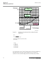


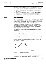


as the harmonic is above the set level. However, when a line is energized the
current setting value
IdMinHigh
is used. Effectively this means that the line A-
B-C in Figure
forms the characteristic. The harmonic block scheme is
generally not applied if there are no in-line or shunt power transformers within
the protection zone. In other words, if there are no in-line or tap (shunt) power
transformers within the protection zone, then no harmonics can prevent a trip
command. This makes the response of the differential protection faster in
approximately 90% of all cases.
•
Current values above the unrestrained limit, gives a trip irrespective of any
presence of harmonics.
•
Classification of a fault as internal by the negative sequence currents based
fault discriminator, gives a trip under the condition that at least one start signal
has been issued, that is, set to 1 (TRUE). The negative sequence current based
fault discriminator itself is not phase-sensitive, and the start signals are
required to determine which phases were affected by the fault. Any harmonic
blocking is then ignored. The harmonic block scheme is not applied if there
are no in-line or tap (shunt) power transformers within the protection zone. In
other words, if there are no in-line or tap power transformers within the
protection zone, then harmonics cannot prevent a trip command. This makes
the response of the protection faster in the majority of cases. If there is no
power transformer within the protected circuit, then the 2
nd
and 5
th
harmonic
analysis is only activated temporarily under external fault conditions, or when
the bias current is lower than 1. 25
ⅹ
IBase
.
•
Classification of a fault as external by the negative sequence fault
discriminator will cause the harmonic logic scheme to be applied under the
duration of the external fault signal, at least for 200 ms. Even the cross block
logic scheme is then active.
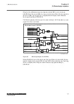
The compensation of charging currents can be selected active or inactive by setting
ChargCurEnable Yes
or
No
. The compensation works so that the fundamental
frequency differential current that is measured under steady state undisturbed
conditions, is identified and then subtracted making the resulting differential
current zero (or close to zero). This action is made separately for each phase. The
magnitude of the subtracted pre-fault currents in Amperes can be read at any time
as the service value ICHARGE.
Values of the pre-fault differential currents are not updated under disturbance
conditions. The updating process is resumed 50 ms after normal conditions have
been restored. Normal conditions are only assumed if there are no start signals,
neither internal nor external fault is declared, the power system is symmetrical.
The change in the charging current that the fault causes by decreasing the system
voltage is not considered in the algorithm. For more information, see the
application manual.
Note that the subtraction of the charging current is limited to a value specified by
IdMin
. Observe as well that
IdMin
must always be set at least 25 % - 50 % above
the value of charging currents.
Section 6
1MRK 505 394-UEN A
Differential protection
100
Line differential protection RED650 2.2 IEC
Technical manual
Summary of Contents for RED650
Page 1: ...RELION 650 SERIES Line differential protection RED650 Version 2 2 Technical manual...
Page 2: ......
Page 36: ...30...
Page 46: ...40...
Page 232: ...226...
Page 272: ...266...
Page 288: ...282...
Page 306: ...300...
Page 406: ...400...
Page 436: ...430...
Page 502: ...496...
Page 614: ...608...
Page 628: ...622...
Page 644: ...638...
Page 760: ...754...
Page 778: ...772...
Page 814: ...808...
Page 870: ...864...
Page 874: ...868...
Page 924: ...918...
Page 925: ...919...


