


zero sequence current is relatively high due to a source with low Z0/Z1 ratio. In
these situations zone measurement will be released both for the related phase-to-
earth loops and the phase-to-phase loop simultaneously. On the other hand,
simultaneous faults closer to the remote bus will gradually take on the properties of
a phase-to-phase-earth fault and the function will eventually use phase-to-phase
zone measurements also here.
In cases where the fault current infeed is more or less completely of zero sequence
nature (all phase currents in phase), the measurement will be performed in the
phase-to-earth loops only for a phase-to-phase-earth fault.
Should it be desirable to use phase-to-earth (and only phase-to-earth) zone
measurement for phase-to-phase-earth faults, there is a setting
INReleasePE
that
can be lowered from its excessive default value to the level above which phase-to-
earth measurement should be activated.
7.1.7.4
Directional criteria
GUID-24431EEC-5037-41CD-BC4A-7AC196F158F3 v5
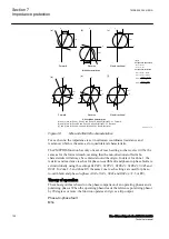
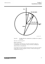
Several criteria are employed when making the directional decision. The basis is
provided by comparing a positive sequence based polarizing voltage with phase
currents. For extra security, especially in making a very fast decision, this method
is complemented with an equivalent comparison where, instead of the phase
current, the change in phase current is used. Moreover, a basic negative sequence
directional evaluation is taken into account as a reliable reference during high load
condition. Finally, a zero sequence directional evaluation is used whenever there is
more or less exclusive zero sequence in-feed.
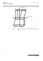
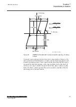
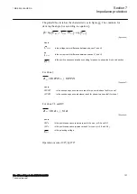
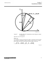
The directional sectors that represent forward direction, one per measuring loop,
are defined by the following equations.
− ° <
<
°
15
120
1
1
arg
U
I
PolL
L
IECEQUATION15059 V1 EN-US
(Equation 4)
− ° <
<
°
15
120
1 2
1 2
arg
U
I
PolL L
L L
IECEQUATION15060 V1 EN-US
(Equation 5)
Where:
U
PolL1
is the polarizing voltage for phase L1.
I
L1
is the phase current in phase L1.
U
PolL1L2
is the polarizing voltage difference between phase L1 and L2 (L2 lagging L1).
I
L1L2
is the current difference between phase L1 and L2 (L2 lagging L1).
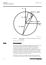
The corresponding reverse directional sectors range from 165 to -60 degrees.
Section 7
1MRK 505 394-UEN A
Impedance protection
120
Line differential protection RED650 2.2 IEC
Technical manual
Summary of Contents for RED650
Page 1: ...RELION 650 SERIES Line differential protection RED650 Version 2 2 Technical manual...
Page 2: ......
Page 36: ...30...
Page 46: ...40...
Page 232: ...226...
Page 272: ...266...
Page 288: ...282...
Page 306: ...300...
Page 406: ...400...
Page 436: ...430...
Page 502: ...496...
Page 614: ...608...
Page 628: ...622...
Page 644: ...638...
Page 760: ...754...
Page 778: ...772...
Page 814: ...808...
Page 870: ...864...
Page 874: ...868...
Page 924: ...918...
Page 925: ...919...


