


1 2
L L
U
1 2
1
L L
set
I
Z
2
1 2
1 2
(
1 )
comp
L L
L L
set
U
U
I
Z
1
1 2
1 2
1
comp
L L
L L
set
U
U
I
Z
1 2
L L
I
jX
1 2
L L
I
R
1 2
1
L L
set
I
Z
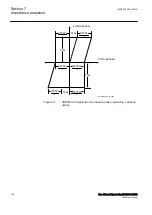
IEC15000058-2-en.vsdx
IEC15000058 V2 EN-US
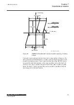
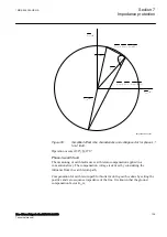
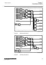
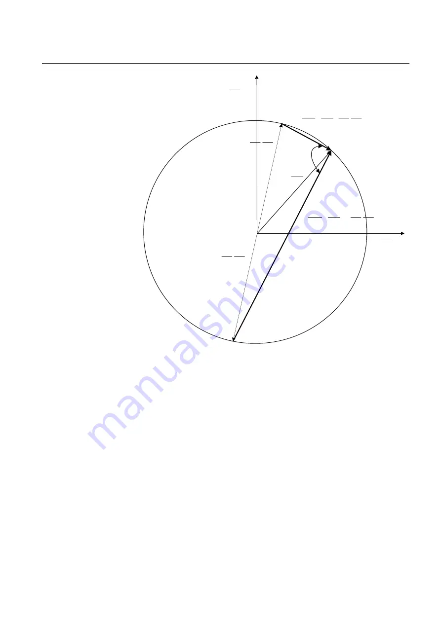
Figure 50:
Simplified offset mho characteristic and voltage vector for phase L1
to L2 fault
Operation occurs if 90°≤β≤270 °.
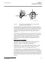
Phase-to-earth fault
SEMOD154224-283 v2
GUID-DB8CF641-0D3F-4F7A-A628-829F3DB0AC5B v1
The measuring of earth faults uses earth return compensation applied in a
conventional way. The compensation voltage is derived by considering the
influence from the earth return path.
Compensation for earth return path for faults involving earth is done by setting the
positive and zero sequence impedance of the line. It is known that the ground
compensation factor K
N
is,
1MRK 505 394-UEN A
Section 7
Impedance protection
Line differential protection RED650 2.2 IEC
129
Technical manual
Summary of Contents for RED650
Page 1: ...RELION 650 SERIES Line differential protection RED650 Version 2 2 Technical manual...
Page 2: ......
Page 36: ...30...
Page 46: ...40...
Page 232: ...226...
Page 272: ...266...
Page 288: ...282...
Page 306: ...300...
Page 406: ...400...
Page 436: ...430...
Page 502: ...496...
Page 614: ...608...
Page 628: ...622...
Page 644: ...638...
Page 760: ...754...
Page 778: ...772...
Page 814: ...808...
Page 870: ...864...
Page 874: ...868...
Page 924: ...918...
Page 925: ...919...


