


R
jX
ArgLd
ArgLd
RLdOutFw
RLdInFw
R1FInFw
R1FInRv
RLdInRv
RLdOutRv
X1InFw
X1OutFw
ZL
R1LIn
X1InRv
X1OutRv
IEC09000222_1_en.vsd
D
Rv
D
Rv
D
Rv
D
Rv
D
Rv
D
Fw
D
Fw
D
Fw
D
Fw
D
Fw
D
Fw
j
j
j
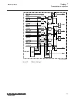
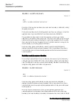
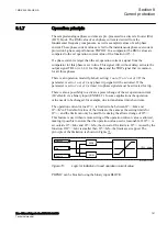
IEC09000222 V1 EN-US
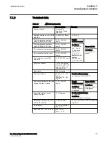
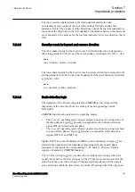
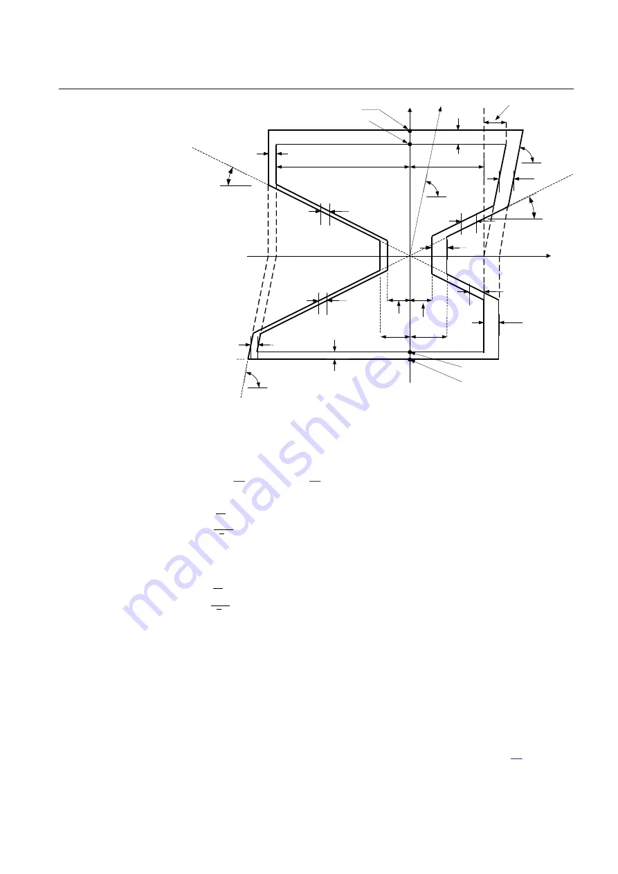
Figure 66:
Operating characteristic for ZMRPSB function (setting parameters
in italic)
The impedance measurement within ZMRPSB function is performed by solving
equation
(n = 1, 2, 3 for each corresponding phase L1, L2 and
L3).
R
set
Re
n
n
I
U
L
L
£
÷÷
ø
ö
çç
è
æ
EQUATION1183 V2 EN-US
(Equation 13)
I
m
n
n
X
set
I
U
L
L
£
÷÷
ø
ö
çç
è
æ
EQUATION1184 V2 EN-US
(Equation 14)
The R
set
and X
set
are R and X boundaries.
7.2.6.1
Resistive reach in forward direction
M13877-6 v3
To avoid load encroachment, the resistive reach is limited in forward direction by
setting the parameter
RLdOutFw
which is the outer resistive load boundary value
while the inner resistive boundary is calculated according to equation
1MRK 505 394-UEN A
Section 7
Impedance protection
Line differential protection RED650 2.2 IEC
149
Technical manual
Summary of Contents for RED650
Page 1: ...RELION 650 SERIES Line differential protection RED650 Version 2 2 Technical manual...
Page 2: ......
Page 36: ...30...
Page 46: ...40...
Page 232: ...226...
Page 272: ...266...
Page 288: ...282...
Page 306: ...300...
Page 406: ...400...
Page 436: ...430...
Page 502: ...496...
Page 614: ...608...
Page 628: ...622...
Page 644: ...638...
Page 760: ...754...
Page 778: ...772...
Page 814: ...808...
Page 870: ...864...
Page 874: ...868...
Page 924: ...918...
Page 925: ...919...


