


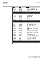
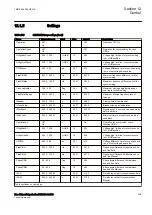


Name
Values (Range)
Unit
Step
Default
Description
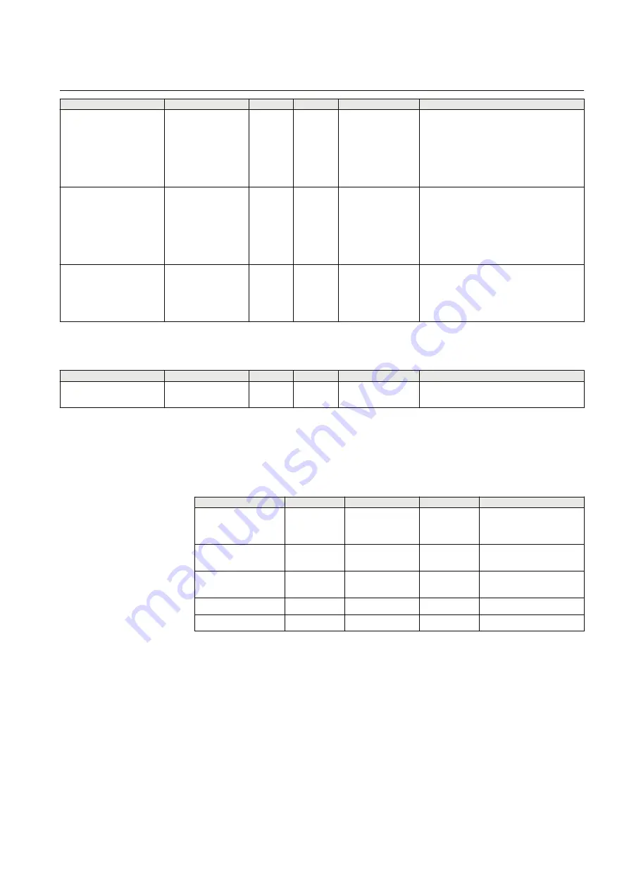
SelPhaseLine1
Phase L1
Phase L2
Phase L3
Phase L1L2
Phase L2L3
Phase L3L1
Positive sequence
-
-
Phase L1
Select phase for line1
SelPhaseLine2
Phase L1
Phase L2
Phase L3
Phase L1L2
Phase L2L3
Phase L3L1
Positive sequence
-
-
Phase L1
Select phase for line2
CBConfig
No voltage sel.
Double bus
1 1/2 bus CB
1 1/2 bus alt. CB
Tie CB
-
-
No voltage sel.
Select CB configuration
Table 167:
SESRSYN Non group settings (advanced)
Name
Values (Range)
Unit
Step
Default
Description
PhaseShift
-180 - 180
Deg
1
0
Additional phase angle for selected line
voltage
12.1.6
Monitored data
PID-6724-MONITOREDDATA v1
Table 168:
SESRSYN Monitored data
Name
Type
Values (Range)
Unit
Description
UDIFFME
REAL
-
-
Calculated difference of
voltage in p.u of set
voltage base value
FRDIFFME
REAL
-
Hz
Calculated difference of
frequency
PHDIFFME
REAL
-
deg
Calculated difference of
phase angle
UBUS
REAL
-
kV
Bus voltage
ULINE
REAL
-
kV
Line voltage
12.1.7
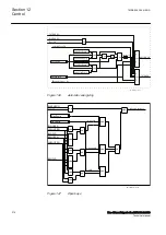
Operation principle
12.1.7.1
Basic functionality
M14832-3 v8
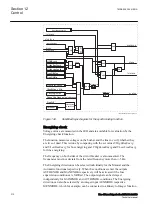
The synchrocheck feature measures the conditions across the circuit breaker and
compares them to set limits. The output for closing operation is given when all
measured quantities are simultaneously within their set limits.
1MRK 505 394-UEN A
Section 12
Control
Line differential protection RED650 2.2 IEC
307
Technical manual
Summary of Contents for RED650
Page 1: ...RELION 650 SERIES Line differential protection RED650 Version 2 2 Technical manual...
Page 2: ......
Page 36: ...30...
Page 46: ...40...
Page 232: ...226...
Page 272: ...266...
Page 288: ...282...
Page 306: ...300...
Page 406: ...400...
Page 436: ...430...
Page 502: ...496...
Page 614: ...608...
Page 628: ...622...
Page 644: ...638...
Page 760: ...754...
Page 778: ...772...
Page 814: ...808...
Page 870: ...864...
Page 874: ...868...
Page 924: ...918...
Page 925: ...919...


