


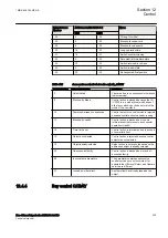
IEC16000159-1-en.vsdx
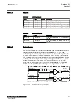
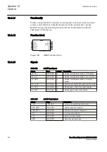
AND
OR
q
-1
AND
20ms
start
THOLHOLD
inhibit
startThermal
inhibitThermalStart
AND
S
R
IEC16000159 V1 EN-US
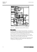
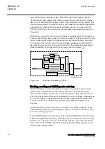
Figure 158:
Thermal protection hold
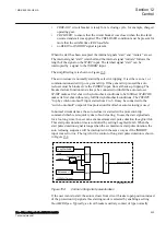
The auto recloser is set as master or slave in multi-breaker arrangements with
sequential reclosing with the setting
Priority
. The auto recloser for the first circuit
breaker, e.g. near the busbar, is set as master (when
Priority
=High) and the auto
recloser for the second circuit breaker is set as slave (when
Priority
=Low). While
the master is in progress, it issues the
WFMASTER
output. After an unsuccessful
reclosing the
WFMASTER
output is also maintained by the
UNSUCCL
output.
When activating the
WAIT
input, in the auto recloser set as slave, every dead timer
is changed to the value of setting
tSlaveDeadTime
and holds back the auto
reclosing operation. When the
WAIT
input is reset at the time of a successful
reclosing of the first circuit breaker, the slave is released to continue the reclosing
sequence after the set
tSlaveDeadTime
. The reason for shortening the time, for the
normal dead timers with the value of
tSlaveDeadTime
, is to give the slave
permission to react almost immediately when the
WAIT
input resets. The mimimum
settable time for
tSlaveDeadTime
is 0.1sec because both master and slave should
not send the breaker closing command at the same time. The slave should take the
duration of the breaker closing time of the master into consideration before sending
the breaker closing command. A setting
tWaitForMaster
sets a maximum wait time
for the
WAIT
input to reset. If the wait time expires, the reclosing cycle of the slave
is inhibited. The maximum wait time,
tWaitForMaster
for the second circuit
breaker is set longer than the auto reclosing dead time plus a margin for
synchrocheck conditions to be fulfilled for the first circuit breaker. Typical setting
is 2sec. In single circuit breaker applications, the setting
Priority
is set to None.
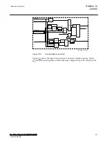
The logic for master-slave is shown in Figure
.
1MRK 505 394-UEN A
Section 12
Control
Line differential protection RED650 2.2 IEC
341
Technical manual
Summary of Contents for RED650
Page 1: ...RELION 650 SERIES Line differential protection RED650 Version 2 2 Technical manual...
Page 2: ......
Page 36: ...30...
Page 46: ...40...
Page 232: ...226...
Page 272: ...266...
Page 288: ...282...
Page 306: ...300...
Page 406: ...400...
Page 436: ...430...
Page 502: ...496...
Page 614: ...608...
Page 628: ...622...
Page 644: ...638...
Page 760: ...754...
Page 778: ...772...
Page 814: ...808...
Page 870: ...864...
Page 874: ...868...
Page 924: ...918...
Page 925: ...919...


