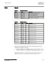

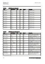

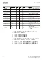

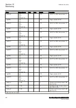
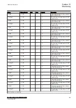
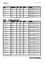
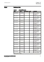
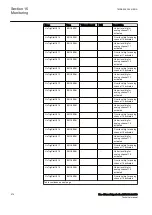
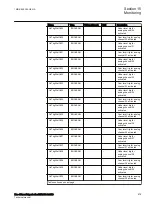


Name
Values (Range)
Unit
Step
Default
Description
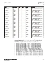
IndicationMa09
Hide
Show
-
-
Show
Indication mask for binary channel 9
TrigLevel10
Trig on 0
Trig on 1
-
-
Trig on 1
Trigger on positive (1) or negative (0)
slope for binary input 10
IndicationMa10
Hide
Show
-
-
Show
Indication mask for binary channel 10
TrigLevel11
Trig on 0
Trig on 1
-
-
Trig on 1
Trigger on positive (1) or negative (0)
slope for binary input 11
IndicationMa11
Hide
Show
-
-
Show
Indication mask for binary channel 11
TrigLevel12
Trig on 0
Trig on 1
-
-
Trig on 1
Trigger on positive (1) or negative (0)
slope for binary input 12
IndicationMa12
Hide
Show
-
-
Show
Indication mask for binary channel 12
TrigLevel13
Trig on 0
Trig on 1
-
-
Trig on 1
Trigger on positive (1) or negative (0)
slope for binary input 13
IndicationMa13
Hide
Show
-
-
Show
Indication mask for binary channel 13
TrigLevel14
Trig on 0
Trig on 1
-
-
Trig on 1
Trigger on positive (1) or negative (0)
slope for binary input 14
IndicationMa14
Hide
Show
-
-
Show
Indication mask for binary channel 14
TrigLevel15
Trig on 0
Trig on 1
-
-
Trig on 1
Trigger on positive (1) or negative (0)
slope for binary input 15
IndicationMa15
Hide
Show
-
-
Show
Indication mask for binary channel 15
TrigLevel16
Trig on 0
Trig on 1
-
-
Trig on 1
Trigger on positive (1) or negative (0)
slope for binary input 16
IndicationMa16
Hide
Show
-
-
Show
Indication mask for binary channel 16
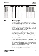
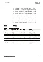
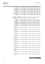
GUID-8702C5B9-05A3-4E61-8952-C66483FFDFE2 v3
B2RBDR to B22RBDR functions have the same Non group settings (basic) as
B1RBDR but with different numbering (examples given in brackets):
•
B2RBDR: 17 to 32 (SetLED17, set LED on HMI for binary channel 17)
•
B3RBDR: 33 to 48 (SetLED33, set LED on HMI for binary channel 33)
•
B4RBDR: 49 to 64 (SetLED49, set LED on HMI for binary channel 49)
•
B5RBDR: 65 to 80 (SetLED65, set LED on HMI for binary channel 65)
•
B6RBDR: 81 to 96 (SetLED81, set LED on HMI for binary channel 81)
•
B7RBDR: 97 to 112 (SetLED97, set LED on HMI for binary channel 97)
•
B8RBDR: 113 to 128 (SetLED113, set LED on HMI for binary channel 113)
•
B9RBDR: 129 to 144 (SetLED129, set LED on HMI for binary channel 129)
•
B10RBDR: 145 to 160 (SetLED145, set LED on HMI for binary channel 145)
•
B11RBDR: 161 to 176 (SetLED161, set LED on HMI for binary channel 161)
•
B12RBDR: 177 to 192 (SetLED177, set LED on HMI for binary channel 177)
•
B13RBDR: 193 to 208 (SetLED193, set LED on HMI for binary channel 193)
•
B14RBDR: 209 to 224 (SetLED209, set LED on HMI for binary channel 209)
1MRK 505 394-UEN A
Section 15
Monitoring
Line differential protection RED650 2.2 IEC
571
Technical manual
Summary of Contents for RED650
Page 1: ...RELION 650 SERIES Line differential protection RED650 Version 2 2 Technical manual...
Page 2: ......
Page 36: ...30...
Page 46: ...40...
Page 232: ...226...
Page 272: ...266...
Page 288: ...282...
Page 306: ...300...
Page 406: ...400...
Page 436: ...430...
Page 502: ...496...
Page 614: ...608...
Page 628: ...622...
Page 644: ...638...
Page 760: ...754...
Page 778: ...772...
Page 814: ...808...
Page 870: ...864...
Page 874: ...868...
Page 924: ...918...
Page 925: ...919...


