
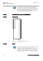

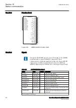
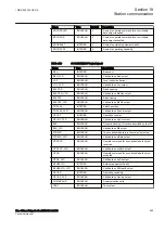

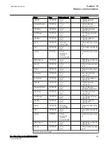

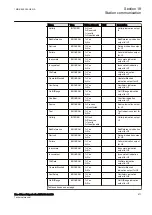
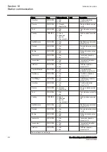


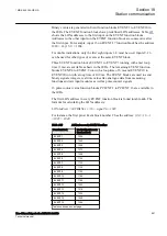


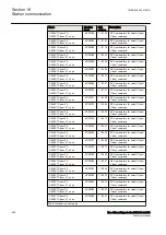
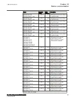


Name
Type
Values (Range)
Unit
Description
OperatorBlocked
BOOLEAN
1=Yes
0=No
-
OperatorBlocked
indication output for U4
Oscillatory
BOOLEAN
1=Yes
0=No
-
Oscillatory indication
output for U4
OutOfRange
BOOLEAN
1=Yes
0=No
-
OutOfRange indication
output for U4
Overflow
BOOLEAN
1=Yes
0=No
-
Overflow indication
output for U4
Source
BOOLEAN
0=Process
1=Substituted
-
Source indication output
for U4
Test
BOOLEAN
1=Yes
0=No
-
Test indication output for
U4
Validity
INTEGER
0=Good
2=Reserved
1=Invalid
3=Questionable
-
Validity indication output
U4
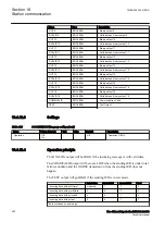
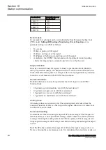
18.5.6
Operation principle
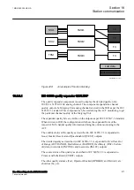
GUID-A1D31CDA-1FE2-4BC0-A472-1B35E73CA1F2 v4
The merging units (MUs) are situated close to the primary equipment, like circuit
breakers, isolators, etc. The MUs have the capability to gather measured values
from measuring transformers, non-conventional transducers or both. The gathered
data are then transmitted to subscribers over the process bus, utilizing the
IEC/UCA 61850-9-2LE protocol.
The IED communicates with the MUs over the process bus via the rear access
points. For the user, the MU appears in the IED as a normal analogue input module
and is engineered in the very same way.
1MRK 505 394-UEN A
Section 18
Station communication
Line differential protection RED650 2.2 IEC
673
Technical manual
Summary of Contents for RED650
Page 1: ...RELION 650 SERIES Line differential protection RED650 Version 2 2 Technical manual...
Page 2: ......
Page 36: ...30...
Page 46: ...40...
Page 232: ...226...
Page 272: ...266...
Page 288: ...282...
Page 306: ...300...
Page 406: ...400...
Page 436: ...430...
Page 502: ...496...
Page 614: ...608...
Page 628: ...622...
Page 644: ...638...
Page 760: ...754...
Page 778: ...772...
Page 814: ...808...
Page 870: ...864...
Page 874: ...868...
Page 924: ...918...
Page 925: ...919...


