L1
IED
L2
132
2
110
2
kV
V
1
3
2
132
2
110
2
kV
V
IEC16000140-1-en.vsdx
4
SMAI2
BLOCK
^GRP2L1
^GRP2L2
^GRP2L1L2
^GRP2N
AI2P
AI1
AI2
AI3
AI4
AIN
5
IEC16000140 V1 EN-US
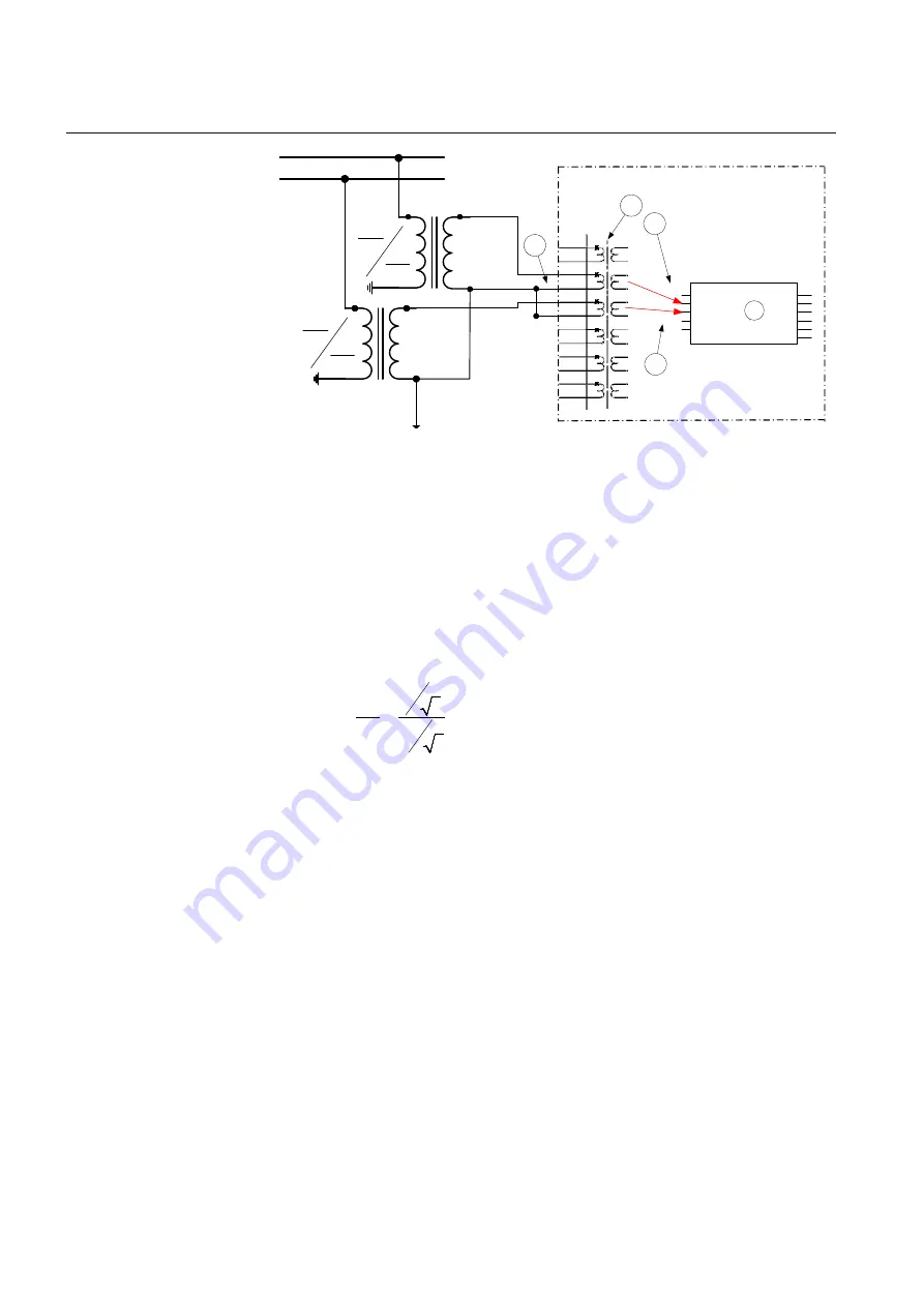
Figure 18:
A two phase-to-earth connected VT
Where:
1)
shows how to connect three secondary phase-to-earth voltages to three VT inputs on
the IED
2)
is the TRM where these three voltage inputs are located. For these three voltage
inputs, the following setting values shall be entered:
VTprim =132 kV
VTsec = 110 V
Inside the IED, only the ratio of these two parameters is used. It shall be noted that the
ratio of the entered values exactly corresponds to ratio of one individual VT.
66
66
3
110
110
3
=
EQUATION1903 V1 EN-US
(Equation 2)
Table continues on next page
Section 4
1MRK 505 393-UEN B
Analog inputs
58
Line differential protection RED650 2.2 IEC
Application manual
Summary of Contents for RED650
Page 1: ...RELION 650 SERIES Line differential protection RED650 Version 2 2 Application manual ...
Page 2: ......
Page 22: ...16 ...
Page 32: ...26 ...
Page 82: ...76 ...
Page 112: ...106 ...
Page 152: ...146 ...
Page 208: ...202 ...
Page 214: ...208 ...
Page 282: ...276 ...
Page 356: ...350 ...
Page 404: ...398 ...
Page 408: ...402 ...
Page 442: ...436 ...
Page 452: ...446 ...
Page 453: ...447 ...


