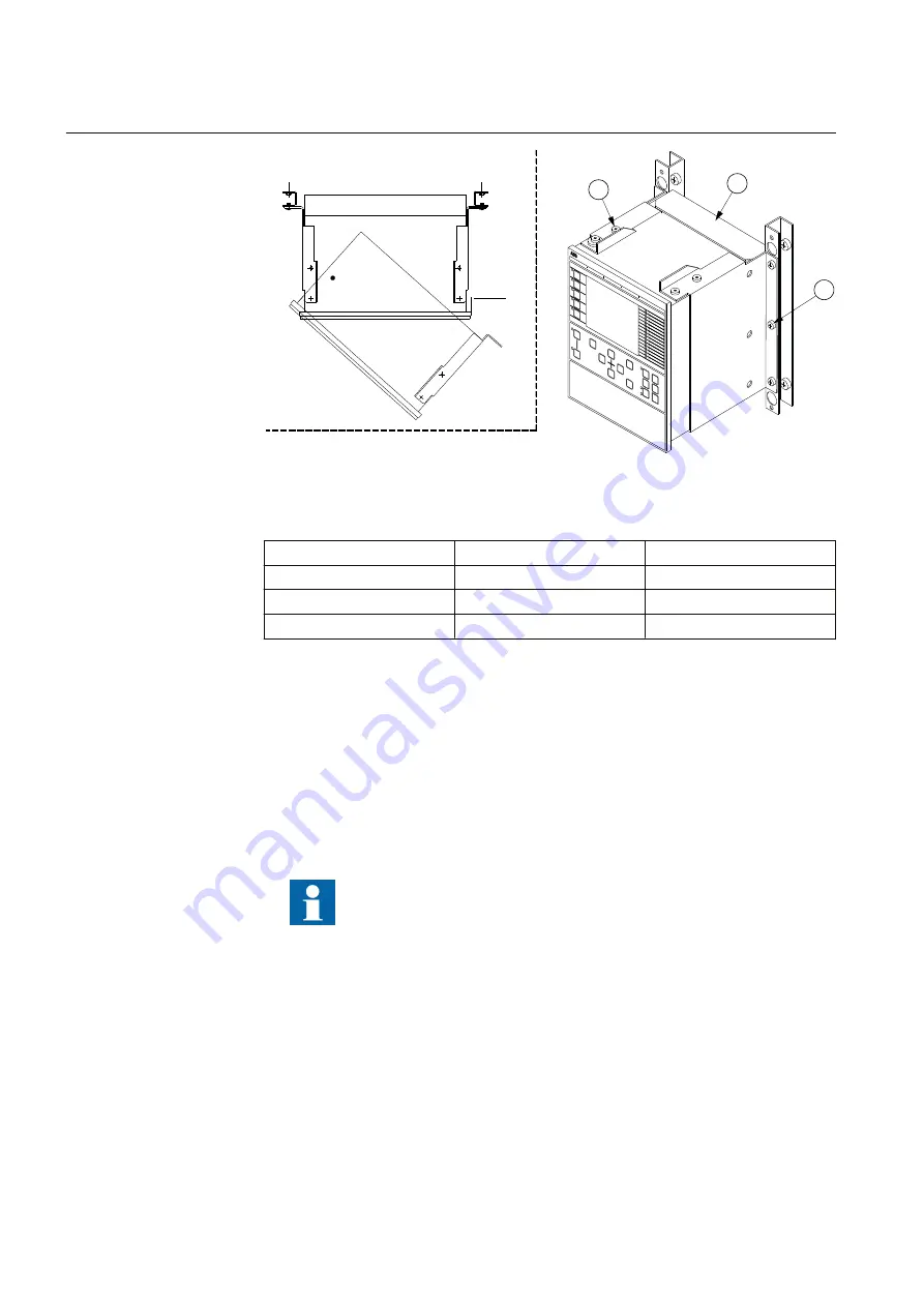
80 mm
1
3
2
IEC06000135-2-en.vsd
IEC06000135 V3 EN-US
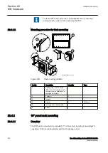
Figure 402:
How to reach the connectors on the rear side of the IED.
PosNo
Description
Type
1
Screw
M4x10
2
Screw
M5x8
3
Rear protection cover
(Ordered separately)
22.4.4
Side-by-side 19” rack mounting
IP10323-1 v1
22.4.4.1
Overview
M11974-3 v3
IED case size 1/2 x 19” and RHGS cases can be mounted side-by-side up to a
maximum size of 19”. For side-by-side rack mounting, the side-by-side mounting
kit together with the 19” rack panel mounting kit must be used. The mounting kit
has to be ordered separately.
Use only the screws included in the mounting kit when mounting
the plates and the angles on the IED. Screws with wrong dimension
may damage the PCBs inside the IED.
Section 22
1MRK 505 394-UEN A
IED hardware
856
Line differential protection RED650 2.2 IEC
Technical manual
Summary of Contents for RED650
Page 1: ...RELION 650 SERIES Line differential protection RED650 Version 2 2 Technical manual...
Page 2: ......
Page 36: ...30...
Page 46: ...40...
Page 232: ...226...
Page 272: ...266...
Page 288: ...282...
Page 306: ...300...
Page 406: ...400...
Page 436: ...430...
Page 502: ...496...
Page 614: ...608...
Page 628: ...622...
Page 644: ...638...
Page 760: ...754...
Page 778: ...772...
Page 814: ...808...
Page 870: ...864...
Page 874: ...868...
Page 924: ...918...
Page 925: ...919...

