Feeder Terminal
REF 542plus
1MRS756269
General (cont´d)
5
A070117
Fig. 4
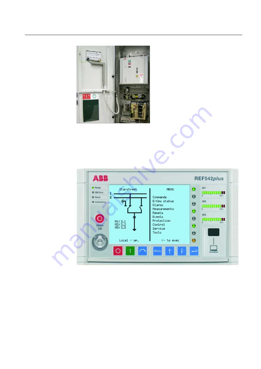
Mounting of the base unit in the LV compartment and the HMI on the door.
The HMI control unit, Fig. 5, features a back-
illuminated liquid crystal display (LCD),
eight push buttons, several LEDs and an elec-
tronic key interface. The language of the dis-
play can be selected by using the related
software on the Configuration Tool CD
(1MRS151062). The same software is also
used to define the protection and the control
scheme.
A050399
Fig. 5
HMI control unit.
The left side of the LCD display is reserved
for the single line diagram. The right side is
for plain text visualization such as measure-
ment and protection events. The LCD back-
light is switched off automatically after 20
minutes of inactivity.
The HMI is a complete system for the local
management of the switchgear. The HMI
allows the operator to set the protection func-
tions, operate the primary objects, visualize
measurements and events, reset alarms and
change the unit working mode.
Summary of Contents for REF 542plus
Page 1: ...Feeder Terminal Product Guide REF 542plus...
Page 2: ......


