

Feeder Terminal
REF 542plus
1MRS756269
8
Design
Software design
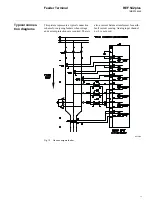
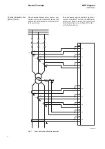
Analog inputs
REF 542plus switchbay feeder terminal is
designed for connecting to non-conventional
current and voltage sensors as well as to
instrument transformers.
At most 8 analog input channels are avail-
able. Due to their linear characteristic, mod-
ern current and voltage sensors provide
greater accuracy and reliability in signal mea-
surements. Compared to instrument trans-
formers, the new non-inductive sensors have
the following advantages:
•
higher linearity
•
high accuracy
•
compact dimensions
•
wide dynamic range
•
easy integration in the panels.
The current sensor is based on the Rogowsky
coil principle and consists of a single air-
wounded coil. Due to the lack of an iron core,
the saturation effects of conventional current
transformers do not exist anymore. Current
sensors are thus well suited for the deploy-
ment of distance and differential protection
functions.
The voltage sensor is based on the resistive
divider principle. Therefore, the voltage sen-
sor is linear throughout the whole measuring
range. The output signal is a voltage, directly
proportional to the primary voltage.
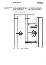
Binary inputs and outputs
The REF 542plus unit acquires the primary
objects status with auxiliary contacts, which
are read by binary inputs, and sends com-
mands using binary outputs. Several signals
coming from other components are also mon-
itored.
Among others, the following operations are
implemented using binary inputs and outputs:
•
primary objects control and interlocking
in the switchgear
•
primary objects status acquisition (for
example circuit breaker in opened/closed
position)
•
circuit breaker spring supervision (when
applicable).
Binary inputs are isolated by opto-couplers.
Binary outputs can be implemented either
with mechanical relays or with static (semi-
conductor) devices. In a switchgear with
directly driven motors, static power outputs
are usually required.
Interfacing a station automation system
An optional communication module can be
provided for interfacing a station automation
system. The four different protocols available
for the REF 542plus make possible to inter-
face any kind of station automation system,
both from ABB or from third parties.
The following typical functions are possible:
•
primary objects status monitoring
•
primary objects control
•
protections parameterization
•
measurements, alarms end events acquisi-
tion
•
fault recorder data acquisition.
The available protocols are:
•
SPA
•
ABB LON according to LON Application
Guide (LAG) 1.4 definitions
•
MODBUS RTU
•
MODBUS TCP
•
IEC 60870-5-103 with the extensions for
control functions according to VDEW
(Vereinigung Deutscher Elektriz-
itätswerke = Association of German Utili-
ties)
• IEC 61850 (only vertical communication)
The first two protocols, SPA and LON
according to LAG 1.4, are ABB specific. The
LON LAG 1.4 protocol has specific features
for high accuracy time synchronization. In
this case, the REF 542plus units are synchro-
nized from the interbay bus. The other proto-
cols, MODBUS RTU, MODBUS TCP and
IEC 60870-5-103 guarantee open connectiv-
ity to any third party system. In case of com-
munication to a Profibus DP control system is
required, a corresponding gateway SPA-ZC
302 can be used.
Summary of Contents for REF 542plus
Page 1: ...Feeder Terminal Product Guide REF 542plus...
Page 2: ......