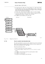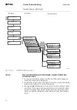
Main Menu
Group Menu
Parameter Menu
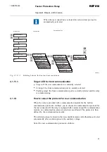
MEASUREMENTS
Confirm
Cancel
OPERATION
LOCKOUT RESET
OPERATION
TRIP LOCKOUT
RECORDED DATA
OPERATION
SETTINGS
CONFIGURATION
INFO
A040239
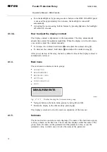
Fig. 4.1.10.-1
Resetting trip lockout function
4.1.11.
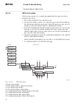
How to switch between front and rear connection
There are two means of serial communication available for the relay: the front
connection for SPA bus communication and optional rear communication modules
for communication via the SPA bus, IEC 60870-5-103, MODBUS (RTU or ASCII)
protocol or DNP 3.0 protocol.
If the relay is not provided with an optional rear communication
module, or if the module has been disabled, the front connection is
always active and switching between front and rear connection is not
allowed.
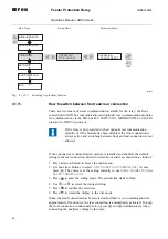
If the optional rear communication module is installed and enabled, the default
setting is the rear connection. Switch between front and rear connection as follows:
1. Press an arrow button to access the main menu.
2. Use the arrow buttons to select
CONFIGURATION\COMMUNICATION
and
press
. The cursor is at the setting currently in use (
REAR CONNECTION
or
FRONT CONNECTION
).
3. Press
to enter the setting mode. The second line starts to flash.
4. Use
or
to select the wanted setting.
5. Press
to confirm the selection.
6. Press
to return the display to the idle mode.
When the front connection has been selected and there is no communication for
approximately five minutes, the rear connection is automatically activated. To keep
the front connection continuously active, press
and
simultaneously when
connecting the auxiliary voltage to the relay.
24
REF 610
REF 610
Feeder Protection Relay
Operator's Manual - ANSI Version
1MRS755539


