27
*
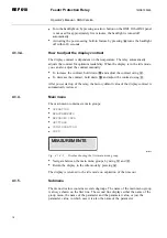
Stored event values from the protection functions
*
Registered number of pickups of protection functions
*
Continuously updated registers of actual values from protection functions
*
OPERATION
*
Resetting of trip lockout
*
INFO
*
Information on the relay, such as device type and relay serial number
4.2.1.2.
How to monitor measured values
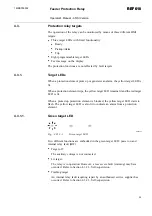
You can monitor all measured values via
MEASUREMENTS
in the HMI menu. In
addition, the measured current values on phases I
a
, I
b
and I
c
and the measured value
of I
n
can also be monitored by activating the monitoring state.
To access the measured values on phases I
a
, I
b
and I
c
and the measured value of I
n
,
I
(unbal)
and TH LEVEL via the HMI menu:
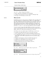
1. Press an arrow button to access the main menu.
2. The cursor is at the first menu item,
MEASUREMENTS
. Press
to see the
measured value on phase I
a
.
3. Use
and
to monitor the measured values on phases I
a
, I
b
and I
c
and the
measured value of I
n
, I
(unbal)
and TH LEVEL. The phase currents are shown as
multiples of the rated current I
n
. I
n
is shown as a percentage of the rated current,
I
n
, while I
(unbal)
is shown as a percentage of the highest phase current and TH
LEVEL is shown as a percentage of the thermal trip level. Press
once more to
see the corresponding primary current value for L1, L2, L3 and I
0
current value
for I
a
, I
b
, I
c
and I
n
. If the conversion factors are set to zero, dashes "
- - -
" are
displayed instead.
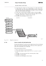
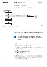
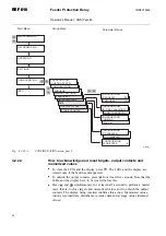
4. Use the arrow buttons to monitor other measured values in the menu
DEMAND
VALUES
; see Fig. 4.2.1.2.-1.
5. Press
to return the display to the idle mode.
Feeder Protection Relay
Operator's Manual - ANSI Version
REF 610
REF 610
1MRS755539


