


2
3
3
1
0, 5
2
j
a
e
j
p
×
= ×
= -
+
IECEQUATION00022 V1 EN
7.
Compare the result with the set value of the negative-sequence operating
current. Consider that the set value 3I2< is in percentage of the base current
IBase.
6.8.1.3
Measuring the operate value for the zero-sequence function
1.
Simulate normal operating conditions with the three-phase currents in phase
with their corresponding phase voltages and with all of them equal to their rated
values.
2.
Slowly decrease the measured voltage in one phase until the BLKU signal
appears.
3.
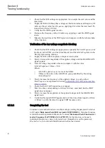
Record the measured voltage and calculate the corresponding zero-sequence
voltage according to the equation.
Observe that the voltages in the equation are phasors.
3 U
0
×
U
L1
U
L2
U
L3
+
+
=
IEC00000276 V1 EN
(Equation 43)
Where:
U
L1
, U
L2
and U
L3
IEC00000275 V1 EN
= the measured phase voltages
4.
Compare the result with the set value (consider that the set value
3U0>
is in
percentage of the base voltage of the zero-sequence operating voltage.
5.
and
. Then slowly increase the measured current in one phase
until the BLKU signal disappears.
6.
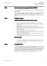
Record the measured current and calculate the corresponding zero-sequence
current according to the equation.
Observe that the currents in the equation are phasors.
0
L1
L2
L3
3
=
I
I
I
I
×
+
+
IECEQUATION00019 V1 EN
(Equation 45)
Where:
1
2
3
L
L
L
I
I and I
,
IECEQUATION00020 V1 EN
= the measured phase currents
7.
Compare the result with the set value of the zero-sequence operating current.
Consider that the set value 3I0< is in percentage of the base current IBase.
6.8.1.4
Checking the operation of the du/dt and di/dt based function
Section 6
1MRK 502 049-UEN A
Testing functionality
96
Commissioning manual


