


Values of the logical signals for UV2PTUV are available on the local HMI under
Main menu/Tests/Function status/Voltage/UV2PTUV(27,2U<)/UV2PTUV:1
.
The Signal Monitoring in PCM600 shows the same signals that are available on the
local HMI.
6.6.1.1
Verifying the setting
Verification of START value and time delay to operate for Step 1
1.
Check that the IED settings are appropriate, especially the START value, the
definite time delay and the
1 out of 3
operation mode.
2.
Supply the IED with three-phase voltages at their rated values.
3.
Slowly decrease the voltage in one of the phases, until the START signal
appears.
4.
Note the operate value and compare it with the set value.
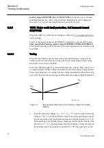
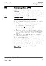
The operate value in secondary volts is calculated according to
the following equations:
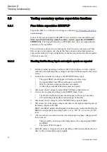
For phase-to-ground measurement:
U
UBase
VT
VTprim
1
100
3
<
×
×
sec
IECEQUATION2430 V1 EN
(Equation 23)
For phase-to-phase measurement:
U
UBase
VT
VTprim
1
100
<
×
×
sec
IECEQUATION2431 V1 EN
(Equation 24)
5.
Increase the measured voltage to rated load conditions.
6.
Check that the START signal resets.
7.
Instantaneously decrease the voltage in one phase to a value about 20% lower
than the measured operate value.
8.
Measure the time delay for the TRIP signal, and compare it with the set value.
9.
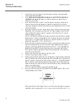
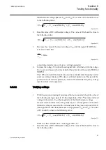
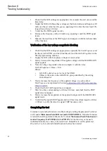
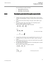
Check the inverse time delay by injecting a voltage corresponding to 0.8 × U1<.
For example, if the inverse time curve A is selected, the trip
signals TR1 and TRIP operate after a time corresponding to the
equation:
t s
k
U
U
( )
=
−
<
1
1
1
IECEQUATION2428 V1 EN
(Equation 25)
where:
t(s)
Operate time in seconds
1MRK 502 049-UEN A
Section 6
Testing functionality
81
Commissioning manual


