sinusoidal currents will flow from the very beginning. In this case the waveform block
algorithm removes all its three block signals in a very short interval of time. This quick
reset of the waveblock criterion will temporarily disable the second harmonic
blocking feature of the differential protection function. This consequently ensures fast
operation of the transformer differential function for a switch onto a fault condition.
It shall be noted that this feature is only active during initial power transformer
energizing, more exactly, under the first 50 ms. When the switch onto fault feature is
disabled by the setting parameter
SOTFMode
, the waveblock and second harmonic
blocking features work in parallel and are completely independent from each other.
6.1.3.13
Logic diagram
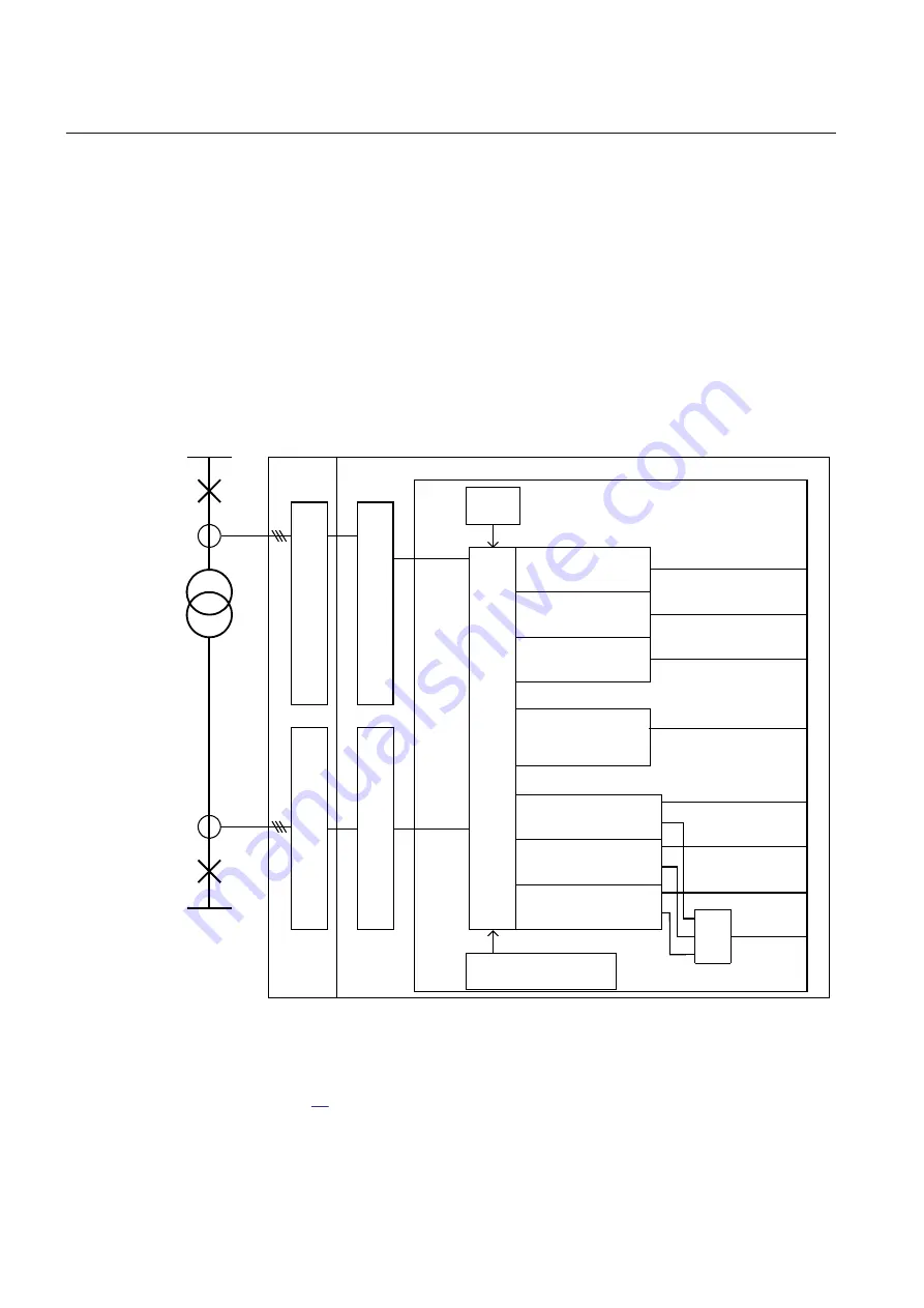
The simplified internal logics, for transformer differential protection are shown in the
following figures.
ADM
A
/D
c
on
ve
rs
io
n
s
ca
lin
g
w
ith
C
T
ra
tio
A
/D
c
on
ve
rs
io
n
s
ca
lin
g
w
ith
C
T
ra
tio
P
ha
so
r
ca
lc
ul
at
io
n
o
f i
nd
iv
id
u
al
ph
as
e
c
ur
re
nt
P
ha
so
r
ca
lc
ul
at
io
n
o
f i
nd
iv
id
u
al
ph
as
e
c
ur
re
nt
Differential function
D
er
iv
e
e
qu
at
io
n
to
c
al
cu
la
te
d
iff
er
e
nt
ia
l c
ur
re
nt
s
Trafo
Data
P
ha
so
rs
&
s
a
m
pl
es
P
ha
so
rs
&
s
a
m
pl
es
Instantaneous (sample based)
Differential current, phase L1
Instantaneous (sample based)
Differential current, phase L2
Instantaneous (sample based)
Differential current, phase L3
Fundamental frequency (phasor
based) Diff current, phase L1 &
phase current contributions from
individual windings
Fundamental frequency (phasor
based) Diff current, phase L2 &
phase current contributions from
individual windings
Fundamental frequency (phasor
based) Diff current, phase L3 &
phase current contributions from
individual windings
Negative sequence diff current
& NS current contribution from
individual windings
IEC09000162_1_en.vsd
MAX
Settings for Zer. Seq.
Current Reduction
IDL1MAG
IDL2MAG
IDL3MAG
IDNSMAG
IDL2
IDL1
IDL3
IBIAS
IEC09000162 V1 EN
Figure 37:
Treatment of measured currents within IED for transformer differential function
shows how internal treatment of measured currents is done in case of a two-
winding transformer.
Section 6
1MRK 502 048-UEN A
Differential protection
104
Technical manual
Summary of Contents for REG650 ANSI
Page 1: ...Relion 650 series Generator protection REG650 Technical manual ...
Page 2: ......
Page 36: ...30 ...
Page 42: ...36 ...
Page 50: ...44 ...
Page 64: ...58 ...
Page 86: ...80 ...
Page 262: ...256 ...
Page 300: ...294 ...
Page 438: ...432 ...
Page 476: ...470 ...
Page 592: ...586 ...
Page 664: ...658 ...
Page 678: ...672 ...
Page 726: ...720 ...
Page 727: ...721 ...


