I.L. 40-385.7
3-2
NOTE:
IOM is used to supervise all ground units and IM is used to supervise all phase units,
including Zone 1,2,3 and pilot for tripping.
3.2.1
Single-Phase-to-Ground
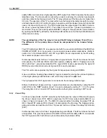
Single-phase-to-ground fault detection (see Figure 3-2, page 3-28) is accomplished by three
self-polarized phase-ground units (ph-A, ph-B, ph-C). Equations (1) and (2) below are for Op-
erate and Reference quantities, respectively. The unit will produce output when the Operate
quantity leads the Reference quantity in phase angle. The Operate quantity is essentially iden-
tical to that in REL300 Version 2.2 and earlier relays. The Reference quantity is changed from
earlier versions, in order to produce a fixed mho characteristic which will have better perfor-
mance when applied to resistance grounded systems. The “forward” reach applies to the oper-
ate (trip) direction of the unit, while the “reverse” reach applies to the restraint direction and is
used primarily to define the overall size of the characteristic and the amount of reach along the
R-axis. (In the case of the reversible Zone-3, the “forward” reach actually is in the reverse line
direction, since that is the direction where tripping takes place; the “reverse reach is then in the
forward line direction.)
(1)
(2)
Z
0L
, Z
1L
=
zero and positive sequence line impedance in relay ohms
Z
CGF
, Z
CGR
=
zone forward and reverse reach settings in secondary ohms of Z1L, for ph-
G fault (both are in angle PANG)
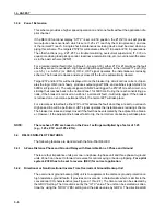
As in the standard REL300, these units are directionally supervised by FDOG (RDOG for re-
verse zone three). Because of internal clipping of unfaulted phase voltages during phase-
ground faults, use of
only ZSEQ or DUAL polarization of DIRU is recommended when ap-
plied to resistance grounded systems; calculation of V2 magnitude and angle is likely to be in-
correct in this application, causing NSEQ polarization to give false directional sense (see
Section 3.4.11).
V
XG
I
X
k
O
I
O
+
[
]
Z
CGF
–
k
o
Z
OL
Z
IL
–
Z
IL
------------------------
Z
R
GANG
PANG
–
(
)
1
–
∠
=
=
I
O
1
3
--- I
A
I
B
I
C
+
+
(
)
=
j V
XG
I
X
k
O
I
O
+
[
]
Z
CGR
+
(
)
Where V
XG
V
AG
V
BG
or V
CG
,
,
=
I
X
I
A
I
B
or I
C
, ,
=
Summary of Contents for REL-300
Page 26: ......
Page 28: ......
Page 29: ...I L 40 385 7 1 12 Figure 1 4 Simplified Block Diagram of REL300 Relay Sub 6 9651A07 ...
Page 36: ......
Page 37: ......
Page 38: ......
Page 39: ......
Page 40: ......
Page 41: ......
Page 42: ......
Page 43: ...I L 40 385 7 2 13 Figure 2 8 REL300 Outline Drawing Sub 2 2403F38 ...
Page 44: ...I L 40 385 7 2 14 Figure 2 9 REL300 Backplane Rear View Sub 11 2420F01 ...
Page 71: ...I L 40 385 7 3 27 Figure 3 1 REL300 Characteristics R X Diagram 9651A57 Sub 3 ...
Page 74: ...I L 40 385 7 3 30 Figure 3 5 REL300 Zone 1 Trip Logic 9661A16 Sub 1 ...
Page 75: ...I L 40 385 7 3 31 Figure 3 6 REL300 Zone 2 Trip Logic 9658A84 Sub 2 ...
Page 76: ...I L 40 385 7 3 32 Figure 3 7 REL300 Zone 3 Trip Logic 1504B04 Sub 1 ...
Page 78: ...I L 40 385 7 3 34 Figure 3 10 Loss of Potential Logic 9662A61 Sub 1 ...
Page 83: ...I L 40 385 7 3 39 Figure 3 17 Load Loss Accelerated Trip Logic 9656A33 Sub 2 ...
Page 85: ...I L 40 385 7 3 41 Figure 3 19 Reclosing Initiation Logic 1504B45 Sub 1 ...
Page 88: ...I L 40 385 7 3 44 Figure 3 24 PUTT Keying Logic Sub 2 9657A62 ...
Page 89: ...I L 40 385 7 3 45 Figure 3 25 Blocking System Logic 1504B89 Sub 1 ...
Page 94: ...I L 40 385 7 3 50 Figure 3 33 Composite Signal For Programmable Output Contacts Sub 2 1504B08 ...
Page 110: ...I L 40 385 7 4 13 Figure 4 1 REL300 Backplate Sub 8 1354D22 Sheet 4 of 5 ...
Page 111: ...I L 40 385 7 4 14 Figure 4 2 REL300 Backplane PC Board Terminals Sub 1 1611C78 ...
Page 112: ...I L 40 385 7 4 15 Figure 4 3 REL300 Systems External Connection Sub 3 1502B21 ...
Page 169: ...I L 40 385 7 B 7 Figure B 2 Test Connection for Three Phase Faults 1502B51 Sub 1 Sheet 2 of 4 ...
Page 181: ......
Page 182: ......
Page 183: ......
Page 184: ......

