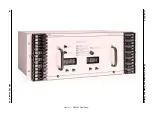
Power Automation and Protection Division
I.L. 40-201.9
REL 352 Version 1.00
1-3
1
1.5
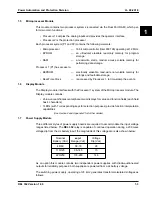
Microprocessor Module
This module contains two processor systems (connected via the Dual Port RAM), which per-
form two main functions:
• Processor 1 samples the analog inputs and provides the operator interface
• Processor 2 is the protection processor
Each processor system (P1 and P2) contains the following elements:
• Microprocessor
— 16 bit microcontroller (Intel 80C196) operating at 12 MHz.
• EPROM
— an ultraviolet erasable read-only memory for program
storage.
• RAM
— a read-write, static, random access volatile memory for
performing data storage.
Processor 1 (P1) has access to:
• EEPROM
— electrically erasable, read-write non-volatile memory for
settings and fault-data storage.
• Real-Time Clock
— is accessed by Processor 1, to time-stamp the events.
1.6
Display Module
The Display module interfaces with the Processor 1 system of the Microprocessor module. The
Display module contains:
• 2 blue-vacuum fluorescent alphanumeric displays for value and function fields (each field
has 4 characters)
• 7 LEDs (with 7 corresponding keys for selection purposes) provide function interpretation
capabilities
(
See Section 4 and Appendix F for further details)
1.7
Power Supply Module
Three different styles of power supply boards are required to accommodate the input voltage
ranges listed below. The REL 352 relay is capable of continued operation during a 200 msec
voltage dip from the dc battery input; the magnitude of this voltage dip is also shown below:
As an option this module contains two independent power supplies, with diode-auctioneered
outputs for reliability purposes; both supplies are powered from a dc battery voltage.
The switching power supply, operating at 25 kHz, generates transformer-isolated voltages as
follows:
Nominal
Battery (Vdc)
Input
Range (Vdc)
Voltage
Dip (Vdc)
48/60
38-70
28
110/125
88-145
73
220/250
176-280
146


