I.L. 40-201.9
Power Automation and Protection Division
3-2
REL 352 Version 1.00
2.
COMPOSITE SEQUENCE FILTER PHASE COMPARISON
Current only systems, like the REL 352, compare the currents measured at the terminals of the
transmission line. In a phase comparison system, like the REL 352, the phase relationship de-
termines whether the condition is internal or external.
For an internal fault, the currents are essentially “in phase” at the terminals of the transmission
line. For an external fault; the currents are 180˚ out of phase. Figure 3-1 illustrates the concept.
The REL 352 combines the phase current (IA, IB and IC) measured at the protective relaying
terminal into a single quantity. This quantity is an output of Symmetrical Component Filter which
is proportional to the weighted sum of the sequence components. Figure 3-2 illustrates this fil-
ter.
The quantity IT, therefore, is defined as:
(3.1)
The quantity IT is itself a sine wave. The C1 (positive sequence weighting coefficient), C2 (neg-
ative sequence weighting coefficient) and C0 (zero sequence weighting coefficient) are system
settings that control the sensitivity of the relaying system.
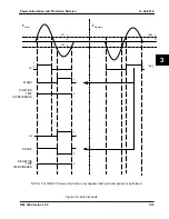
The sinusoidal waveform IT is converted into square-waves for phase comparison as illustrated
in Figure 3-3.
2.1.
Local Positive (LP) and Local Negative (LN)
These waveforms are used to represent a phase of positive and negative half-cycle of the IT
signal at a local terminal.
The local positive LP is defined as a logic “1” in the positive region of IT above the setting LP;
otherwise it is a “0”.
The local negative LN is defined as a logic “1” in the negative region of IT below the setting LN;
otherwise it is a “0”.
Notice, that the local negative level, LN, is implicitly defined as the negative LP level,
i.e., LN = LP.
2.2.
IKEY
The IKEY level is provided to divide the threshold generating the squarewave to be sent to the
remote terminal. The IKEY level is defined in the positive region. Above the threshold level, the
local terminal will “key” a logic “1” to the remote terminal.
The recommended setting of IKEY is the same as the LP setting.
3.
FSK POWER LINE CARRIER AND AUDIO TONE APPLICATIONS
Internal Fault
The signals generated during an internal fault are shown in Figure 3-4. Note that the local and
remote currents are essentially in phase. The local terminal generates the LP and LN signals.
IT
C0I 0
C1I 1
C2I 2
+
+
=


