I.L. 40-201.9
Power Automation and Protection Division
3-4
REL 352 Version 1.00
6.
PILOT TRIP LOGIC
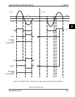
Figure 3-7 illustrates the decision logic for the REL 352. The comparison signal, COUT feeds
into a 4 millisecond timer (supervised by FD2, fault detector signal explained later). For security
purposes, to account for inaccuracies and transmission line charging current effects, a mini-
mum width of the squarewave logic “1” level is required. This is accomplished through a pick-
up timer of 4 milliseconds.
If the setting in the logic indicates a ONE count requirement (CNT = 1) it implies that a COUT sig-
nal that generates a pulse of at least 4 milliseconds will indicate a trip condition and PLT = “1”.
If the setting CNT = 2 indicating a TWO count requirement, more security is introduced in the
trip decision. For this setting, COUT should produce two logic “1” pulses of at least 4 millisec-
onds within a 25 millisecond period (for FSK PLC) or 40 msec (for ON-OFF PLC) to assert the
pilot trip PLT = “1”. In the event that the first pulse is greater than 6 milliseconds, indicating a
robust fault, a bypass timer produces the trip on the first count. Security is improved if the two
count setting is used.
The trip (PLT) signal is enabled as long as FD2 is active. Figure 3-8 illustrates the components
of FD2.
The FD2 unit is a fault detector that is measuring the output of the sequence filter, IT. The signal
IT can be thought of as current and the setting for FD2 as the setting of a normal overcurrent
unit. It is recommended that FD2 be set below the minimum three-phase fault magnitude and
above the maximum expected load current (multiplied by the respective coefficients C0, C1 and
C2).
The system, for added security, provides another faster and reliable fault detector. This fault
detector, denominated CD, measures the relative change in the current (or voltage) quantities.
The input currents and voltages are sampled 12 times per power line cycle, the magnitudes
most recent samples are compared to the corresponding samples 1 cycle “ago”. If the relative
magnitude difference exceeds 12.5% of the previous value the CD is asserted.
An OR function combines all the change detector units into a single signal (CD) as illustrated
in Figure 3-9. It is always advisable to include the voltage change detectors (CD=
∆
V
∆
I) if the
external voltage transformers are connected to REL 352.
Moreover, for weakfeed terminals, voltage change detectors are highly recommended.
7.
OPTIONAL BACK-UP
7.1.
Distance Relaying
The Distance units in the REL 352 relay system are only operative when the communications
channel is unsound. The back-up distance relaying system only includes Zone 2 and Zone 3 of
a conventional non-pilot distance relaying system.
Line measurement techniques applied to each zone include:
• Single phase-to-ground fault detection
• 3-Phase fault detection
• Phase-to-phase fault detection
• Phase-to-phase-to-ground fault detection


