Power Automation and Protection Division
I.L. 40-201.9
REL 352 Version 1.00
4-5
4
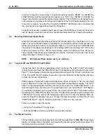
4.4.1. Contact Input Test
The Contact Input module (Appen-
dix D) can be conveniently tested,
using the Contact Input Test Func-
tion.
To activate this function, continually
depress the DISPLAY key until the
“TEST” LED is illuminated. Then
depress the “FUNCTION RAISE’ or
“FUNCTION LOWER” key until the
word “OPTI” appears in the FUNC-
TION field.
The “VALUE” field will display the
status of the contact inputs, using
two hexadecimal digits, as ex-
plained below.
When the contacts close (voltage is applied across two input terminals), the corresponding bit
is set to binary “1”; an open set of contacts results in a binary “0”. The following correspondence
exists:
FUNCTION
BIT NUMBER
Not used
0
Stub Bus
1
Not used
2
Target Reset
3
52b
4
Not Used
5
Not Used
6
Not Used
7
For Example:
The functions listed below,
• Target Reset
(closed)
• 52b contact
(closed)
• Remaining contacts
(open)
will result in the following binary pattern:
Bit Pattern
0 0 0 1
1 0 0 0
Bit Number
7 6 5 4
3 2 1 0
HEX “Value”
Field Display
1
8
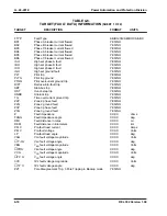
For reference, refer to Table 4-2 for the binary-to-hexadecimal conversion.
Table 4-1:
Test Mode Functions
Functi
on
Description
STAT
TEST
TLDT
SRT
OPTI
TRIP
BFI
SRI
3RI
R B
GS
FALM
TALM
CALM
Relay Self-Check Status
Phase comparison TEST ENABLE Signal
Test Mode Computation of Local Delay Time
Monitor Standing Relay Trip Signal
Display Opto Input Status
Relay Test:Trip Relays
Relay Test:BFI Relays
Relay Test:SRI Relay (RI1)
Relay Test:3RI Relay (RI2)
Relay Test:Reclose Block Relay
Relay Test:General Start Relay
Relay Test:Failure Alarm Relay
Relay Test:Trip Alarm Relay
Relay Test:Channel Alarm Relay


