LINE SECTIONALIZING USING A PLC AND ABB PROTECTIVE RELAY
Page 7 of 53
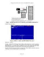
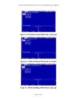
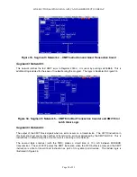
NETWORK 4 – FIGURE 7:
This is the MSTR send instruction which is parameterized for read and write commands. The upcounter
in the logic counts the number of good network transactions (00104 energizes on a GOOD
communication and 00103 energizes on a bad communication, 00102 is the instruction active indication).
It should be noted that although 125 registers may be read/written at any one time, the program has been
limited to Modbus Plus data accesses of 30 registers (to conserve PLC memory). The data is stored in
4X memory 40110 through 40149.
Figure 7. Segment 1 Network 4 – Master Polling Block
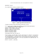
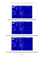
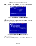
NETWORK 5 – Figure 8:
The UCTR in this network counts the BAD Modbus Plus network transfers (an excellent indicator for
network troubleshooting and program troubleshooting). This network also determines when an network
access has finished executing. The TMR in this network construct places a dwell time of 200 mS
between each Modbus Plus network transaction.
Figure 8. Ladder Logic Dwell Timer and Bad Transaction Network
Summary of Contents for REL 356
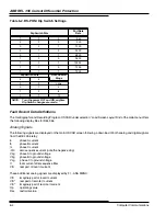
Page 23: ...ABB REL 356 Current Differential Protection 1 10 Product Overview and Specifications ...
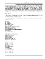
Page 83: ...ABB REL 356 Current Differential Protection 3 36 Settings and Application ...
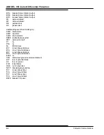
Page 127: ...ABB REL 356 Current Differential Protection 5 28 Testing ...
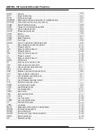
Page 186: ...LINE SECTIONALIZING USING A PLC AND ABB PROTECTIVE RELAY Page 49 of 53 ...
Page 187: ...LINE SECTIONALIZING USING A PLC AND ABB PROTECTIVE RELAY Page 50 of 53 ...
Page 188: ...LINE SECTIONALIZING USING A PLC AND ABB PROTECTIVE RELAY Page 51 of 53 ...
Page 189: ...LINE SECTIONALIZING USING A PLC AND ABB PROTECTIVE RELAY Page 52 of 53 ...


